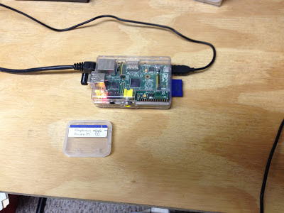
I kind of got interested in Bluetooth yesterday and what I might be able to do with it and my iPhone. I thought that I might start with an audio server since there were a number of articles on how to set this up. This is a real quick and dirty setup. So my hardware consists of:
- Raspberry Pi
- Powersupply and powered hub
- IOGear GBU521 bluetooth USB adapter
- Sabrent USB-SBCV audio adapter
I merged instructions from three locations:
https://www.modmypi.com/blog/installing-the-raspberry-pi-nano-bluetooth-dongle
http://www.raspberrypi.org/phpBB3/view topic.php?f=35&t=26685
http://www.ioncannon.net/linux/1570/bluetooth-4-0-le-on-raspberry-pi-with-bluez-5-x/
Bluetooth setup steps
1. do the usual "sudo raspi-config" to ensure that the defaults are set up right on the RPi
2. sudo apt-get update
3. install the Bluetooth audio related packages with "sudo apt-get install bluetooth bluez-utils blueman pulseaudio pulseaudio-module-bluetooth alsa-base alsa-utils pavucontrol"
4. note, lots of things installed here including printer drivers (bluetooth printing interface)
5. edits according to the raspberrypi.org article
6. plug in IOGear GBU521 bluetooth usb adapter, reboot
7. run bluetooth manager from control panel, sync up iPhone and RPi
8. setup loopback according to the raspberrypi.org article
9. play a tune from the iPhone, works!
Now I need to set up the Sabrent USB-SBCV audio adapter for better sound quality. I am looking at http://www.geekytidbits.com/raspberry-pi-unattended-audio-recordings/ for some inspiration.
More Later.

This is a blog mostly about techie things, what I am doing to my apartment network on the cheap, IOT, 3D Printing, Raspberry Pis, Arduinos, ESP32, ESP8266, Home Automation, Personal Weather Stations, Things That Go Bump in the Night, and some side issues that need discussing. Remember, sometimes the journey to an end is as much fun as the goal achieved!
Friday, June 28, 2013
Thursday, June 27, 2013
Started wiring up a test slice from the LED Cube
Well I have started wiring up a test slice from the LED Cube. I am doing this mostly to work out the kinks in the electronics and to make sure that what I think is the correct way of doing it, actually does work. I think that I have a good handle on the problem but time will tell. So far, I have discovered that I am using a large number of breadboard wires. I started by trying a 4x4 vertical slice. In doing this, I have the opportunity to observe the connections for R, G, B, and level and how they interact together. Once I have the circuit wired up, I can concentrate on the interface to the RPi. I have decided to drive this thing from the RPi rather than go through an Arduino this go around. I am gaining more confidence in the RPi and its ability to compute and think through the problem. My interface to the LED Cube is strictly through I2C so there should be no challenges from the 3.3v vs 5v interfaces that seem to plague these projects. Adafruit has a nice discussion on interfacing the RPi to the MCP23017 16 I/O chip that I will be using. I decided to do the interfacing by "slice" which means that I will have 8 "slices" in total for a 8x8x8 LED Cube. It also means that I can get away with 8 levels, 8 Red, 8 Green, and 8 Blue control lines for each slice. That will mean that each slice is independent of the other slices. It also means that I can concentrate on a smaller version at first and build up from there, hence the fact that I am making a 4x4 slice to write my test software on. If I need something bigger than 8x8x8, I can multiply the "slices" in each direction. I just have to write the software knowing that. The breadboard slice is shown below.

Right now it looks like it's going to be two MCP23017s per "slice" or a total of 16. Unfortunately, the addressing scheme on the MCP23017 allows for 8 addresses, so I will be having to bring in a chip such as a PCA9548 to allow for more than one I2C channel. Right now, the concentration is on just the test slice, then I can concentrate on other matters.

Right now it looks like it's going to be two MCP23017s per "slice" or a total of 16. Unfortunately, the addressing scheme on the MCP23017 allows for 8 addresses, so I will be having to bring in a chip such as a PCA9548 to allow for more than one I2C channel. Right now, the concentration is on just the test slice, then I can concentrate on other matters.
Monday, June 24, 2013
Working on a Design for an LED Cube
I have started considering what it would take to build an LED Cube. I originally thought of a 5x5x5, but now am considering a cube as big as 8x8x8. This provides a little more resolution in each direction; which is not a bad thing for putting up characters instead of patterns. What will I do with it? I was thinking of an art object but technical in nature. Besides, what I really want to do is exercise my creativity with electronics and software. That being said the following come to mind:
- It should be made from RGB leds so that the color can be manipulated on each individual led by itself
- The circuitry controlling the leds should be self contained
- Minimize the power required to drive the cube
- Minimize the interface to the circuitry that controls the LEDs to cut down on setup of lines and the overhead involved
- Possibly use an I2C interface to the circuitry to simplify control
- Build the cube in such a way that the circuitry could be modified to be bigger if needed
Friday, June 21, 2013
Development Work on Blackboard System is Still Plodding Along
I can safely say that this Blackboard implementation is taking a long time to design. The real reason is that I only have a short period of time during the day in which I can attack the problem. My job and home life take up a lot of my time and there are precious few moments in which I can be by myself doing the things that I like. That is why I just plod along with the design, touching it here and there throughout the day when I have a moment to myself.
To date, I am trying to come up with a scheme to get the Knowledge Sources created and working within the Blackboard Controller structure. I decided on making the Blackboard Controller run a state chart system as the Control Plan. The first Control Plan executed is a bootstrap which loads the top level control knowledge source. My first implementation of the Top Level Control Knowledge Source (TLC_KS) is driven by a builder pattern. Later on, I will modify this TLC_KS to be able to load it from a set of XML descriptions. That TLC_KS is the main element which causes all of the other knowledge sources to be loaded, some with their own control plans, the blackboard elements, and the top level control plan which orchestrates everything. The top level control plan represents the problem to be solved and is composed of lower level elements arranged in a hierarchy. The nature of a blackboard system is that at any moment a decision could be made to change the plan that is being executed. That change is controlled by knowledge sources that react to the current state of the information on the blackboard.
I am just having fun putting the design together, learning about this type of system, and working through the thought process. So what do you do for fun?
Wednesday, June 19, 2013
I Now Have a Movable TOR Proxy as Part of the Network
I was able to complete the TOR proxy that I wanted to put together. I first followed the instructions at http://learn.adafruit.com/setting-up-a-raspberry-pi-as-a-wifi-access-point/ to get one of the RPis to work as an access point. I then started following the instructions at http://learn.adafruit.com/onion-pi to get the TOR proxy working. I reset my managed switch to have a port open to the outside (my
psuedo-DMZ), plugged in the RPi, and restarted it. I was able to check
it out using http://www.ipchicken.com and found that my ip was coming from the output of a TOR relay. Success ...
I have also opened an identical port to the outside in the third switch that I have in the house. In that way, I am able to move the TOR proxy from one part of the house to the other.
I have also opened an identical port to the outside in the third switch that I have in the house. In that way, I am able to move the TOR proxy from one part of the house to the other.
Monday, June 17, 2013
Thinking of some Proxy add-ons
The TOR proxy seems like a good idea for using a spare RPi. I wouldn't do it if its your only RPi though. Too much of a chance that you will just keep using it over and over. I was thinking of adding a second wireless adapter and making it a wireless-to-wireless proxy instead of a wireless-to-ethernet proxy. In fact I was also thinking of adding a second ethernet to allow a connection via a ethernet switch to the LAN side of the proxy. Then what I would have would be a wireless access port, with the capability of connecting either through a wireless adapter or ethernet on the WAN side and wireless and/or ethernet on the LAN side. I would also want to be able to use shorewall to manipulate the capabilities a little better. Although the Adafruit instructions create a nat firewall that is adequate, I would still like to have a finer resolution on what I will allow. I wonder if this would be a good fit for the 2x16 LCD screen with buttons from Adafruit that I have to be able to set up the correct connections from. Maybe something like this:

In addition, I could use CURL to access the internet through my companies Guest account. There is a Cisco Web Authentication component, hence the need for CURL to authenticate prior to connection. The connection would be something like:
OP=`curl -k -d "buttonClicked=4" -d "err_flag=0" -d "info_flag=0" -d "username=guestname" -d "password=guestpassword" https://wirelesssubdomain.mycompany.com/login.html`;
That would be a very useful item at work and at home. Hmmmm. I have to think some more about this.
The TOR Proxy is Now Running
Well after some false starts and puzzlements, I was able to complete the TOR proxy that I wanted to put together. I first followed the instructions at http://learn.adafruit.com/setting-up-a-raspberry-pi-as-a-wifi-access-point/ to get one of the RPis to work as an access point. The problem that I was having was getting the hostapd to recognize the wireless adapter that I was using. I tried three different wireless adapters (having gone to Staples to get the third) and could not get them to work. When I tried looking through the logs with dmesg, I could see that the adapter was recognized and a driver was immediately launched, but hostapd was not able to work with it even though I put the name of the driver that was launched in the configuration file. Then it dawned on me that having the driver name in the hostapd.conf file might mean that it was trying to install the driver. So I removed it. When I did, hostapd started working correctly. All I can figure out is that I had updated the system and possibly the new version of the system automatically loaded a driver each time it got an adapter that it recognized.
I finished up the install and was able to get the RPi to work as a wi-fi access point, with a simple firewall and nat setup and the other connection through the ethernet port. I then started following the instructions at http://learn.adafruit.com/onion-pi to get the TOR proxy working. The instructions do not have you rebooting the RPi at particular intervals, and that turned out to be the problem child. As soon as I rebooted to a known state, my setup started working as advertised. I reset my managed switch to have a port open to the outside (my psuedo-DMZ), plugged in the RPi, and restarted it. I was able to check it out using http://www.ipchicken.com and found that my ip was coming from the output of a TOR relay. Success ... here is a picture of the finished product for what it is worth.
I finished up the install and was able to get the RPi to work as a wi-fi access point, with a simple firewall and nat setup and the other connection through the ethernet port. I then started following the instructions at http://learn.adafruit.com/onion-pi to get the TOR proxy working. The instructions do not have you rebooting the RPi at particular intervals, and that turned out to be the problem child. As soon as I rebooted to a known state, my setup started working as advertised. I reset my managed switch to have a port open to the outside (my psuedo-DMZ), plugged in the RPi, and restarted it. I was able to check it out using http://www.ipchicken.com and found that my ip was coming from the output of a TOR relay. Success ... here is a picture of the finished product for what it is worth.

Saturday, June 15, 2013
Trying to make a TOR Proxy
It looks like Adafruit came out with a tutorial on "Onion Pi". This is a TOR proxy for the Raspberry Pi. TOR is an anonymizing network. A lot of people have been showing interest in TOR since the issue with the NSA looking into people's information like email and phone calls came to light. I am just interested in the proxy because of the security aspects of it, since I am in the security game now. So later tonight I will go through the instructions.
-- LW
-- LW
Subscribe to:
Posts (Atom)