
This is a blog mostly about techie things, what I am doing to my apartment network on the cheap, IOT, 3D Printing, Raspberry Pis, Arduinos, ESP32, ESP8266, Home Automation, Personal Weather Stations, Things That Go Bump in the Night, and some side issues that need discussing. Remember, sometimes the journey to an end is as much fun as the goal achieved!
Saturday, December 31, 2016
holding off for a bit!
I have decided that I need to take a break from updating this blog. Will be back in the near future.
Thursday, December 29, 2016
IPSec VLAN #2 - Hardening Rules
After review of information in this SANS 2006 document, I am a little more confident that I can implement the Gateway into my house with a more controlled hardening. This document is a design using open source components for an Intrusion Detection/Prevention System. It applies to a small to medium network which is appropriate for my home environment. My thought is to have this implemented prior to the OpenVPN server in the IPSec VLAN setup that I am building. Additionally, I will be using SELinux to lock down the services running on my OpenVPN RPi server. So at this point the following would be needed:
- IDS/IPS in the flow between the internet connection and the OpenVPN server.
- SELinux used to lock down services in the RPi server.
- Checks to make sure that the OpenVPN stream is not broken/compromised, if so then stop all traffic incoming to the home network (meaning the IPSec streams would stop).
- Audit logs of activity and regular checking of the logs to ensure that nothing got by.
- No DHCP service on No Man's Land LAN.
- No ICMP ping responses from any device connected to No Man's Land LAN, this might include any detection of scanning in the network and/or detection of pen test tools.
IPSec VLAN #1 - Keeping VLANs Separate Using Encryption
I was reviewing some Capability Package (CP) documents from NSA the other day and it occurred to me that one of the ideas I could use was to keep VLANs separate from each other even across the internet. This has appeal since I have a couple of VLANs in my home network that are not connected to the outside world or each other, yet I want to be able to do something with them during lunch at work.
Without going into too much detail re: the CP from NSA, they describe a virtual private network using commercial products which keep security domains separate from each other. This is done through a double encryption linkage. The following illustrates what I am talking about:

In this diagram, an OpenVPN Gateway is used on both sides (with certificate based connection) to form a connection between two No Man's Land LANs. This is roughly equivalent to what we normally do on a day to day basis connecting a laptop using an OpenVPN client to our home networks through an OpenVPN server. That being said, the connection goes between two LANs that do nothing in this diagram except give a place to combine packets from multiple IPSec VPN Gateways. If we use a separate certificate to access each "VLAN", the information will not cross between them. In other words, I could have an IPSec VPN Gateway at work, with a certificate for LAN A, and I could only connect through IPSec VPN Gateways at home that used the same certificate. Those would be ones that are part of the same LAN A "VLAN". Notice that I don't have to have a switch/router that is VLAN aware; I could have everything on separate conventional networks.
My thought is to implement OpenVPN on a RPi which would serve as an OpenVPN Gateway into the No Man's Land LAN (after hardening the RPi to attack of course, using a certificate specific to the OpenVPN connection). I would then implement IPSec VPN Gateways on other RPis (also hardened to attack) with certificates specific to the LAN that they connect to. This speaks of having my own certificate authority (which is food for another post). The OpenVPN Gateway doesn't necessarily need to be on an RPi either; I just would like to see if I can get this working using commodity items. Note that the IPSec VPN Gateways could be implemented in VMs as well running on a server.
More Later.
Monday, December 26, 2016
Project #12 - Explore and Add a VPN Capability into the Network
I have been wanting to get a simple connection into my network for a long time now. I have tried some experiments with the Mac Mini using IPSec and have had minimal success. This is a project to be able to get into my network from the outside anytime I am remote from home.
Thursday, December 22, 2016
Change made to network due to Media streaming overload
As luck would have it, the new router that I received from Verizon has a number of issues. One, there is one port on the router that I cannot close because that is used by Verizon to manage their network. As a result, Verizon is able to get inside of the perimeter of the network and is the main reason that I have a second router. Secondly, the Verizon Quantum router does not have vlan capability - at all, nada. This causes some issues with what I want to do in that I need to isolate things to their own broadcast LAN. It doesn't do well to have an Ethernet based media setup which cannot be isolated from other devices that need to share the bandwidth. Also, interestingly enough, I have discovered that pushing a lot of media (and Bonjour messages for that matter) tend to bog this router down.
Verizon likes to be able to check on their cable card which is mounted in a TiVo Bolt on my network. I can understand why they want to do this. They want to be able to control what channels the cable card is able to receive. I have no problem with this in that I am paying for specific parts of their service, they have that right. The reason for the Ethernet traffic is that the TiVo Bolt transmits streams to the two TiVo Minis that I also have in the network. SHMBO occasionally doesn't turn the Minis off when she is done with them and this causes the traffic to continue to stream. She is getting better at it since she has started recording as many as three channels at the same time. Since the Bolt only has 4 tuners, the Mini needs to be stopped after use so that it frees up the tuner that it has captured, but that is another story.
To accommodate the possibility that the connection between the Bolt and a Mini is still active and streaming I have moved the media streaming (Bolt and 2 Minis) to a separate set of Ethernet connections outside of my home network. I am doing this by connecting all of these devices on their own separate Ethernet cables and unmanaged switches, finally ending up coming into a separate unmanaged switch connected to the Quantum router. If the Minis are streaming from the Bolt, the traffic is isolated to the switch and does not affect the Quantum bandwidth. I have also connected the weather station feed through this same set of switches. Normally, only the weather station feed uses the Quantum until we are using either Netflix or Amazon Prime Videos. Meanwhile, if I need to connect to the internet I am free to do so. Best way I know how to accomplish the goals.
Now if I bork something in the home network and it goes down, it doesn't affect the media which makes living with SHMBO much easier. Just a tip to the weary husband that only wants peace in the house.
Wednesday, September 14, 2016
Cluster #4 - Implementing the IPSec VPN as Client and Server
I am working on a solution for security in my house based on an IPSec tunnel. This is partially based on a NSA capability package document re using commercial off-the-shelf encryption techniques for separation of security domains. The idea was interesting enough to try and replicate as part of my home VPN interconnections.
I have been reviewing a number of different posts to get this working, see here, here, and here. Internet Protocol Security (IPsec) is a protocol suite for secure Internet Protocol (IP) communications by authenticating and encrypting each IP packet of a communication session. The major contender package is StrongSwan rather than OpenVPN which does not support IPSec.
I have been reviewing a number of different posts to get this working, see here, here, and here. Internet Protocol Security (IPsec) is a protocol suite for secure Internet Protocol (IP) communications by authenticating and encrypting each IP packet of a communication session. The major contender package is StrongSwan rather than OpenVPN which does not support IPSec.
Saturday, September 3, 2016
Setting up DHCP, NTP, DNS, Radius, and LDAP on a Raspberry Pi
I have been a little bit busy lately and have not had a chance to get back to the RPi things that this blog is all about. Part of that time was learning some things on my new 3D Printer, but that is for another blog post because it will come to play in the future.
I decided that I wanted to setup a simplified server for use on a given vlan and/or a use-case in which I need these services and do not want to rely on a router. So I will need the following services:
Seems like a tall order but it is just setting up things in an orderly manner.
I decided that I wanted to setup a simplified server for use on a given vlan and/or a use-case in which I need these services and do not want to rely on a router. So I will need the following services:
- DHCP - gives out IP addresses for the subnet that it is connected to
- NTP - provides a time service for the subnet
- DNS - provides a localized domain name service for the subnet
- Radius - provides Authentication and Authorization for the subnet, specifically for switches and wireless access points
- LDAP - provides directory services for the Radius server to maintain username/password combinations, allowed MAC addresses, ranges for subnet addresses
- Webmin - provides a web based server update process
Seems like a tall order but it is just setting up things in an orderly manner.
Sunday, July 31, 2016
OpenWRT KVM Setup
I was able to eek out a little period of time this weekend to work on the Ubuntu server. My concentration was on getting some vlans setup coming into the server from a trunk line.
But before that I attempted to setup some OpenWRT VMs using instructions from the openwrt website. First, I downloaded https://downloads.openwrt.org/chaos_calmer/15.05/x86/64/openwrt-15.05-x86-64-combined-ext4.img.gz, then I moved it to the Ubuntu server and unpacked it.
Once that was done, I converted it to qcow2 using the script here. Once that was accomplished I pulled the qcow2 file into KVM and cloned it three times. The three clones are for additional router functions in the future.
Once I had the KVMs generated I then updated the ethernet connection going to the card that had the No-Mans Land vlan on it. I added several more tagged vlans to the trunk that I had formed using the Netgear switch. I then setup a number of vlans using the instructions from https://wiki.ubuntu.com/vlan. I then updated the /etc/network/interfaces file to setup the new vlans from the trunk line (truncated):
# This file describes the network interfaces available on your system
# and how to activate them. For more information, see interfaces(5).
source /etc/network/interfaces.d/*
# The loopback network interface
auto lo br0-vlan6 br2-vlan300 br1-vlan200 enp3s0 enp4s5 enp4s6
iface lo inet loopback
# The primary network interface
iface enp3s0 inet manual
iface br0-vlan6 inet static
address 192.168.0.133
netmask 255.255.255.0
broadcast 192.168.0.255
network 192.168.0.0
gateway 192.168.0.2
bridge_ports enp3s0
bridge_stp off
bridge_fd 0
bridge_waitport 0
dns-nameservers 8.8.8.8 8.8.4.4 192.168.1.1
iface enp4s5 inet manual
...
iface br2-vlan300 inet static
address 10.100.30.50
netmask 255.255.255.0
broadcast 10.100.30.255
network 10.100.30.0
bridge_ports enp4s5
bridge_stp off
bridge_fd 0
bridge_waitport 0
auto enp4s5.4
iface enp4s5.4 inet static
address 10.10.4.45
netmask 255.255.255.0
vlan-raw-device enp4s5
(and so on ...)
Now that I have the vlans (tagged) setup on the same Ethernet as the No-Mans Land vlan, I can concentrate on setting up the OpenWRT VMs to point to the correct vlans.
But before that I attempted to setup some OpenWRT VMs using instructions from the openwrt website. First, I downloaded https://downloads.openwrt.org/chaos_calmer/15.05/x86/64/openwrt-15.05-x86-64-combined-ext4.img.gz, then I moved it to the Ubuntu server and unpacked it.
gunzip openwrt-x86-generic-combined-ext4.img.gz
qemu-img convert -f raw -O vmdk openwrt-x86-generic-combined-ext4.img openwrt-x86-generic-combined-ext4.vmdk
Once that was done, I converted it to qcow2 using the script here. Once that was accomplished I pulled the qcow2 file into KVM and cloned it three times. The three clones are for additional router functions in the future.
Once I had the KVMs generated I then updated the ethernet connection going to the card that had the No-Mans Land vlan on it. I added several more tagged vlans to the trunk that I had formed using the Netgear switch. I then setup a number of vlans using the instructions from https://wiki.ubuntu.com/vlan. I then updated the /etc/network/interfaces file to setup the new vlans from the trunk line (truncated):
# This file describes the network interfaces available on your system
# and how to activate them. For more information, see interfaces(5).
source /etc/network/interfaces.d/*
# The loopback network interface
auto lo br0-vlan6 br2-vlan300 br1-vlan200 enp3s0 enp4s5 enp4s6
iface lo inet loopback
# The primary network interface
iface enp3s0 inet manual
iface br0-vlan6 inet static
address 192.168.0.133
netmask 255.255.255.0
broadcast 192.168.0.255
network 192.168.0.0
gateway 192.168.0.2
bridge_ports enp3s0
bridge_stp off
bridge_fd 0
bridge_waitport 0
dns-nameservers 8.8.8.8 8.8.4.4 192.168.1.1
iface enp4s5 inet manual
...
iface br2-vlan300 inet static
address 10.100.30.50
netmask 255.255.255.0
broadcast 10.100.30.255
network 10.100.30.0
bridge_ports enp4s5
bridge_stp off
bridge_fd 0
bridge_waitport 0
auto enp4s5.4
iface enp4s5.4 inet static
address 10.10.4.45
netmask 255.255.255.0
vlan-raw-device enp4s5
(and so on ...)
Now that I have the vlans (tagged) setup on the same Ethernet as the No-Mans Land vlan, I can concentrate on setting up the OpenWRT VMs to point to the correct vlans.
Thursday, July 14, 2016
Bringing Back the 1-Port Router
Ok, now I need to set up a Raspberry Pi 1-Port Router. I know how to accomplish this (see the article here), I just have to go through the motions to implement it. Strange - I am on SD052; I'm going to have to quit buying these things and start reusing the ones that I already have. The setup was as follows:
sudo apt-get update
sudo apt-get upgrade
sudo apt-get install vlan shorewall
Then to get webmin setup and running, I did the following:
I added to /etc/apt/sources.list -
deb http://download.webmin.com/download/repository sarge contrib
I then got the key for the webmin repository -
sudo wget http://www.webmin.com/jcameron-key.asc
sudo apt-key add jcameron-key.asc
I then installed webmin -
sudo apt-get install perl libnet-ssleay-perl openssl libauthen-pam-perl libpam-runtime libio-pty-perl apt-show-versions python
sudo apt-get install webmin
I am going to use the 1-Port Router to connect between three different vlans, vlan4, vlan6, and vlan8. Webmin will be used to setup the routing functions on Shorewall so that I can do the following:
I am going to accomplish this by the following setup (TBD).
sudo apt-get update
sudo apt-get upgrade
sudo apt-get install vlan shorewall
Then to get webmin setup and running, I did the following:
I added to /etc/apt/sources.list -
deb http://download.webmin.com/download/repository sarge contrib
I then got the key for the webmin repository -
sudo wget http://www.webmin.com/jcameron-key.asc
sudo apt-key add jcameron-key.asc
I then installed webmin -
sudo apt-get install perl libnet-ssleay-perl openssl libauthen-pam-perl libpam-runtime libio-pty-perl apt-show-versions python
sudo apt-get install webmin
I am going to use the 1-Port Router to connect between three different vlans, vlan4, vlan6, and vlan8. Webmin will be used to setup the routing functions on Shorewall so that I can do the following:
- Have a firewall facing out towards vlan4 from vlan6; supply dhcp services to vlan4; allow only traffic from the Mac Mini to vlan4 from vlan6; and provide a one-to-one NAT ip from my WD MyCloud onto vlan4.
- Have a firewall facing out towards vlan8 from vlan6; supply dhcp services to vlan8; allow only traffic from the Mac Mini to vlan8 from vlan6; and provide a one-to-one NAP ip from my ubuntuServer VM cluster.
I am going to accomplish this by the following setup (TBD).
Wednesday, July 13, 2016
Thinking about distributing the network servers
I have been reading up on openvswitch, openflow, and docker and it occurs to me that I might want to take advantage of some of the concepts available to me. I have a VM Server currently that pretty much limits things to the KVM world, each connected to a specific bridge to a hardware port. Those hardware ports in turn are connected to a managed switch. I can do a lot with this setup but I can do better.
One thing that I want to do is distribute the data plane between different VMs and allow for usage of different file servers across my network. I have plenty of space available to me for various files but because of the need to distribute the VMs between different vlans it becomes more difficult without having several hardware routers in the network. I want to use SDN and openvswitch to be able to spread the VM connections around to places that I need them as well as give myself the ability to access any device that I want to. So how would I go about doing this? I have decided to use openvswitch to spread the network access plane around my house without changing the physical network layout of routers and switches. I will instead go the virtual route and apply some Software Defined Network (SDN) concepts.
More Later.
Sunday, July 10, 2016
Project #11 - Use SDN and OpenVSwitch to connect VMs across the Network No-Mans Land
I have been studying up on software define networks and have been looking at OpenVSwitch as a means to run GRE connections across the No-Mans Land vlan.
Sunday, July 3, 2016
Cluster #3 - Rearranged the Cluster for Experimentation
One of the issues that I have fixed is how to take each one of the RPis in the Cluster and be able to independently move them from one location to another. I was able to achieve this by the use of a Netgear 116E 16-port managed switch. Since I have 4 RPis in the cluster, I took up 8 ports on the switch and managed to be able to move things around at my convenience. This was evident when I decided to take .101 and tie it to the same vlan as .100. However, in this case I started up an openVPN setup following the instructions at https://github.com/StarshipEngineer/OpenVPN-Setup. By having .101 on the switch, I was able to easily move the head from the LAN1 vlan to the CEH input vlan. Now I can setup the openVPN independently from what I was intending on doing with .100.
Another interesting tidbit was that I was able to hook up the PowerLine adapter to the No-MansLand vlan in another area in my house and connect to it via the other PowerLine adapter on my front porch. So I was able to do some updates to the RPi while sitting on my porch - and No-MansLand vlan was separated from the outside world. Now what I want to be able to do is access specific vlans from outside using a double IPSec encryption setup. More later.
Another interesting tidbit was that I was able to hook up the PowerLine adapter to the No-MansLand vlan in another area in my house and connect to it via the other PowerLine adapter on my front porch. So I was able to do some updates to the RPi while sitting on my porch - and No-MansLand vlan was separated from the outside world. Now what I want to be able to do is access specific vlans from outside using a double IPSec encryption setup. More later.
Tips #0 - Wow - Amazing Find to Convert VMWare to KVM
I just happened to have enough time over the weekend to look around for some ways to convert from multiple VMWare vmdks to qcow2 and I stumbled across this site. Now that I have found this site I can go about getting some of my VMs into a KVM setup. The bash code that I am using is:
Also found this to convert spaces in names to underscores:
#!/bin/bashfor i in *.vmdk; do qemu-img convert -f vmdk $i -O raw $i.raw; done
cat *.raw > tmpImage.raw
qemu-img convert tmpImage.raw finalImage.qcow2
rm *.raw Also found this to convert spaces in names to underscores:
for f in *\ *; do mv "$f" "${f// /_}"; done Saturday, June 11, 2016
Weather Station Project #27 - Took some samples through material
This morning I was out in the yard setting up an experiment. I connected the Solar Radiation/UV Sensor setup to a POE enabled cable connected to a Ethernet over Power Line adapter. The other Power Line adapter I plugged into my computer downstairs in the computer room. This adapter was plugged into a Pers VLAN connector on one of my GS108Ts. By doing this, I was able to connect to the sensor setup using my laptop on the porch through wi-fi. I am going to leave the connection downstairs so that I will be able to use the Power Line adapter in other VLANS as necessary. It was neat to get it working. Here is a picture of the parts on my porch table.

This UV data shows a loss of about 5 and a half percent in the visible spectrum, 4 and a half percent considering the IR spectrum. The overall percent difference between my local site and the site that I am using for calibration appears to be about 2.8 percent; my value is higher. The distance between us is about 4.13 miles so I have been assuming that the values should be about the same.
According to this data, I should not have a problem if I used the lid to my sandwich container (plastic cover in the test). I just have to compensate for the loss; there doesn't appear to be a loss associated with the UV sensitivity as far as I can tell. So I should multiply my UV readings by 1.0628 to get the same as the Kingstowne values? I should multiply my uvVIS values by 0.4979 to get the watts/m^2 equivalent to the values from the site where I am comparing my values.
The values of the data that I took was as follows:
results with no cover in bright sunlight
{ "tslLUX":"65536.00", "uvVIS":"1677.00", "uvIR":"13354.00", "uvUVRaw":"761.00", "uvUV":"7.61" }
reading from site was 12.0 for UV
Kingstowne says 7.4 UV, 835 watts/m^2
results with plastic cover in bright sunlight
{ "tslLUX":"65536.00", "uvVIS":"1594.00", "uvIR":"12876.00", "uvUVRaw":"716.00", "uvUV":"7.16" }
results with polycarbonate in bright sunlight
{ "tslLUX":"65536.00", "uvVIS":"1600.00", "uvIR":"13228.00", "uvUVRaw":"720.00", "uvUV":"7.20" }
Kingstowne says 6.9 UV, 796 watts/m^2
results with soda glass in bright sunlight
{ "tslLUX":"65536.00", "uvVIS":"1627.00", "uvIR":"12333.00", "uvUVRaw":"734.00", "uvUV":"7.34" }
Kingstowne says 7.2 UV, 833 watts/m^2
results in the shade with no cover
{ "tslLUX":"2152.00", "uvVIS":"312.00", "uvIR":"962.00", "uvUVRaw":"30.00", "uvUV":"0.30" }
{ "tslLUX":"2168.00", "uvVIS":"315.00", "uvIR":"976.00", "uvUVRaw":"31.00", "uvUV":"0.31" }
Kingstowne says 6.7 UV, 817 watts/m^2
According to this data, I should not have a problem if I used the lid to my sandwich container (plastic cover in the test). I just have to compensate for the loss; there doesn't appear to be a loss associated with the UV sensitivity as far as I can tell. So I should multiply my UV readings by 1.0628 to get the same as the Kingstowne values? I should multiply my uvVIS values by 0.4979 to get the watts/m^2 equivalent to the values from the site where I am comparing my values.
Wednesday, June 1, 2016
Weather Station Project #26 - Some more thoughts
After looking through the raw data from my sensor, I discovered a number of points where the data was "pegged". The only thing that I can think of is that the integration time on the sensor was set too high. This is going to require me to redo the sketch that was loaded onto the Arduino. Thinking more about this, I should also attempt to get the final packaging completed for the sensor setup. This means a package that is waterproof and uses POE to power it so that I have but one cable from the POE source to the sensor package. I already have the packaging and I have a few POE splitters on order that will work well with this setup. Now I need to come up with the final specifics.
The list of parts (from here) with some modifications are:
The Raspberry Pi is used to sample from the Arduino. I have proven that I can set up a web service on the Arduino, so accessing it from within my network is a no brainer. I have also proven that I can write a python script which is able to sample both from the Arduino based sensor set and from a Weather Underground station with the sensors that I am trying to emulate. Ultimately the extra sensor base will include:
I have the parts for the Moisture sensor but I am missing the lightning sensor parts. Not sure where to find that.
Update: I got in some POE splitters yesterday so I will probably be building up the package over this weekend. Right now I am just going to use the plastic lid. Will need to get a crystal glass lid so that it will pass UVA and UVB through. I don't think that UVB will be able to pass through the lid at this point.
The list of parts (from here) with some modifications are:
- Raspberry Pi B+
- Arduino Uno
- Arduino Ethernet Shield
- Arduino Proto Board Shield
- TP-Link TL-POE10R PoE Splitter w/power connector cable
- Power splitter cable (1 female to 4 males - 5.5mm x 2.1mm)
- Power adapter plug (1 female 5.5mm x 2.1mm to ISO block)
- Power plug 5.5mm x 2.1mm to micro USB cable
- Ethernet socket adapter (for mounting on wall of sandwich box)
- Clear sandwich box (see-through for RPi camera)
- RTV to pot up the holes so that water can't get in
- Mounting platform and hardware to mount sandwich box on outside
The Raspberry Pi is used to sample from the Arduino. I have proven that I can set up a web service on the Arduino, so accessing it from within my network is a no brainer. I have also proven that I can write a python script which is able to sample both from the Arduino based sensor set and from a Weather Underground station with the sensors that I am trying to emulate. Ultimately the extra sensor base will include:
- Lightning sensor
- Moisture sensor (Transpiration)
- UV monitoring sensor
- Solar radiation sensor
I have the parts for the Moisture sensor but I am missing the lightning sensor parts. Not sure where to find that.
Update: I got in some POE splitters yesterday so I will probably be building up the package over this weekend. Right now I am just going to use the plastic lid. Will need to get a crystal glass lid so that it will pass UVA and UVB through. I don't think that UVB will be able to pass through the lid at this point.
Tuesday, May 31, 2016
Weather Station Project #25 - Back to the Drawing Board
Well, it looks like there is a major problem with my assumptions. Take a look at the following graph:

The red line is the sample from my UV sensor and the green line is the sample from the PWS that has the UV sensor. As you can see, even though my sensor is recording a similar distribution, it is way out of whack. This is more due to cloud cover and the fact that my sensor is not looking up. Also, when I set the sensor up, it was pointed out a window through a screen so there are some artifacts to deal with. The levels are way off here as well. Originally I was going to setup for a sample over an eight day period but I cut that short to be able to see some data.
What I am thinking here is that I need to put the sensors into a different enclosure, one with a glass window. Oh yeah, the solar radiation results were even worse:

Anyway, I need to go back and rethink this thing. More later.
Saturday, May 28, 2016
Weather Station Project #23 - Initial Code for the Solar/UV Sensors
I thought I would take the time to put together some code that will be used in the Solar Radiation and UV Sensors. The objective here is to at least get the sensors tracking and providing data output. I was able to cobble together the sources from the TSL2561 and the SI1145 written by Adafruit along with the source code from the Web Server written by Arduino to get something running. I decided at the last moment to not use a Raspberry Pi but to stick with the Arduino. I have an Arduino Uno, an Ethernet Shield, some extensions and the Arduino breadboard with the two sensors on it (see the following picture).

The code is pretty simple and surprisingly the Serial interface doesn't get in the way (it lets me do the web service without needing to have a console display):
#include <Wire.h>
#include <SPI.h>
#include <Ethernet.h>
#include <Adafruit_Sensor.h>
#include <Adafruit_TSL2561_U.h>
#include "Adafruit_SI1145.h"
/* This sketch is a combination of two sketches from Adafruit
* sensorapi for the TSL2561 lux sensor and si1145test for
* the SI1145 UV sensor. The sketch captures the state of the two
* sensors every minute, waiting for a json request from the ethernet
* port. It then provides a json string back containing the raw and
* computed values of the two sensors.
*
* Please note that the sketch makes use of the Adafruit Sensor API and
* libraries (to make the development simpler).
*
* Connections (TSL2561)
* ===========
* Connect SCL to analog 5
* Connect SDA to analog 4
* Connect VDD to 3.3V DC
* Connect GROUND to common ground
*
* I2C Address (TSL2561)
* ===========
* The address will be different depending on whether you leave
* the ADDR pin floating (addr 0x39), or tie it to ground or vcc.
* The default addess is 0x39, which assumes the ADDR pin is floating
* (not connected to anything). If you set the ADDR pin high
* or low, use TSL2561_ADDR_HIGH (0x49) or TSL2561_ADDR_LOW
* (0x29) respectively.
*
*/
Adafruit_TSL2561_Unified tsl = Adafruit_TSL2561_Unified(TSL2561_ADDR_FLOAT, 12345);
Adafruit_SI1145 uv = Adafruit_SI1145();
// Some more globals to store intermediate info into until asked for by the web intfc
float tslLUX;
float uvVIS;
float uvIR;
float uvUVRaw;
float uvUV;
// Enter a MAC address and IP address for your controller below.
// The IP address will be dependent on your local network:
byte mac[] = {
0xDE, 0xAD, 0xBE, 0xEF, 0xFE, 0xED
};
IPAddress ip(192, 168, 0, 42);
// Initialize the Ethernet server library
// with the IP address and port you want to use
// (port 80 is default for HTTP):
EthernetServer server(80);
/**************************************************************************
* Displays some basic information on this sensor from the unified
* sensor API sensor_t type (see Adafruit_Sensor for more information)
**************************************************************************/
void displayTSL2561Details(void)
{
sensor_t sensor;
tsl.getSensor(&sensor);
Serial.println("------------------------------------");
Serial.print ("Sensor: "); Serial.println(sensor.name);
Serial.print ("Driver Ver: "); Serial.println(sensor.version);
Serial.print ("Unique ID: "); Serial.println(sensor.sensor_id);
Serial.print ("Max Value: "); Serial.print(sensor.max_value); Serial.println(" lux");
Serial.print ("Min Value: "); Serial.print(sensor.min_value); Serial.println(" lux");
Serial.print ("Resolution: "); Serial.print(sensor.resolution); Serial.println(" lux");
Serial.println("------------------------------------");
Serial.println("");
delay(500);
}
/**************************************************************************
* Configures the gain and integration time for the TSL2561
**************************************************************************/
void configureTSL2561(void)
{
/* You can also manually set the gain or enable auto-gain support */
// tsl.setGain(TSL2561_GAIN_1X); /* No gain ... use in bright light to avoid sensor saturation */
// tsl.setGain(TSL2561_GAIN_16X); /* 16x gain ... use in low light to boost sensitivity */
tsl.enableAutoRange(true); /* Auto-gain ... switches automatically between 1x and 16x */
/* Changing the integration time gives you better sensor resolution (402ms = 16-bit data) */
// tsl.setIntegrationTime(TSL2561_INTEGRATIONTIME_13MS); /* fast but low resolution */
// tsl.setIntegrationTime(TSL2561_INTEGRATIONTIME_101MS); /* medium resolution and speed */
tsl.setIntegrationTime(TSL2561_INTEGRATIONTIME_402MS); /* 16-bit data but slowest conversions */
/* Update these values depending on what you've set above! */
Serial.println("------------------------------------");
Serial.print ("Gain: "); Serial.println("Auto");
Serial.print ("Timing: "); Serial.println("402 ms");
Serial.println("------------------------------------");
}
void setup() {
// put your setup code here, to run once:
Serial.begin(9600);
Serial.println("Light Sensor Test"); Serial.println("");
/* Initialise the sensor */
if(!tsl.begin())
{
/* There was a problem detecting the ADXL345 ... check your connections */
Serial.print("Ooops, no TSL2561 detected ... Check your wiring or I2C ADDR!");
while(1);
}
if (!uv.begin()) {
Serial.println("Didn't find Si1145");
while (1);
}
/* Display some basic information on this sensor */
displayTSL2561Details();
/* Setup the sensor gain and integration time */
configureTSL2561();
// start the Ethernet connection and the server:
Ethernet.begin(mac, ip);
server.begin();
Serial.print("server is at ");
Serial.println(Ethernet.localIP());
/* We're ready to go! */
Serial.println("");
}
void loop() {
// put your main code here, to run repeatedly:
/* Get a new sensor event for the lux sensor */
sensors_event_t event;
tsl.getEvent(&event);
/* Display the results (light is measured in lux) */
if (event.light)
{
tslLUX = event.light;
// Serial.print(event.light); Serial.println(" lux");
}
else
{
/* If event.light = 0 lux the sensor is probably saturated
and no reliable data could be generated! */
tslLUX = 0;
// Serial.println("Sensor overload");
}
/* Read the Visible, IR, UV sensor */
// Serial.println("===================");
uvVIS = uv.readVisible();
// Serial.print("Vis: "); Serial.println(uvVIS);
uvIR = uv.readIR();
// Serial.print("IR: "); Serial.println(uvIR);
// Uncomment if you have an IR LED attached to LED pin!
//Serial.print("Prox: "); Serial.println(uv.readProx());
float UVindex;
uvUVRaw = uv.readUV();
UVindex = uvUVRaw;
// the index is multiplied by 100 so to get the
// integer index, divide by 100!
UVindex /= 100.0;
uvUV = UVindex;
// Serial.print("UV: "); Serial.println(UVindex);
// At this point formulate the latest json message to send back on web query
Serial.print("{ "); Serial.print("tslLUX"); Serial.print(" : "); Serial.print(tslLUX);
Serial.print(", "); Serial.print("uvVIS"); Serial.print(" : "); Serial.print(uvVIS);
Serial.print(", "); Serial.print("uvIR"); Serial.print(" : "); Serial.print(uvIR);
Serial.print(", "); Serial.print("uvUVRaw"); Serial.print(" : "); Serial.print(uvUVRaw);
Serial.print(", "); Serial.print("uvUV"); Serial.print(" : "); Serial.print(uvUV);
Serial.println(" }");
// listen for incoming clients
EthernetClient client = server.available();
if (client) {
Serial.println("new client");
// an http request ends with a blank line
boolean currentLineIsBlank = true;
while (client.connected()) {
if (client.available()) {
char c = client.read();
Serial.write(c);
// if you've gotten to the end of the line (received a newline
// character) and the line is blank, the http request has ended,
// so you can send a reply
if (c == '\n' && currentLineIsBlank) {
// send a standard http response header
client.println("HTTP/1.1 200 OK");
client.println("Content-Type: text/html");
client.println("Connection: close"); // the connection will be closed after completion of the response
client.println("Refresh: 5"); // refresh the page automatically every 5 sec
client.println();
client.println("<!DOCTYPE HTML>");
client.println("<html>");
client.print("{ "); client.print("tslLUX"); client.print(" : "); client.print(tslLUX);
client.print(", "); client.print("uvVIS"); client.print(" : "); client.print(uvVIS);
client.print(", "); client.print("uvIR"); client.print(" : "); client.print(uvIR);
client.print(", "); client.print("uvUVRaw"); client.print(" : "); client.print(uvUVRaw);
client.print(", "); client.print("uvUV"); client.print(" : "); client.print(uvUV);
client.print(" }");
client.println("<br />");
client.println("</html>");
break;
}
if (c == '\n') {
// you're starting a new line
currentLineIsBlank = true;
} else if (c != '\r') {
// you've gotten a character on the current line
currentLineIsBlank = false;
}
}
}
// give the web browser time to receive the data
delay(1);
// close the connection:
client.stop();
Serial.println("client disconnected");
}
delay(1000);
}
I did check this out by executing a web call to 192.168.0.42 and was greeted with the json message. I will have to modify this json message later because it doesn't have the quotes around the string values but at least it is working in the short term. I am going to simply put this up in my window at home and sample through a vertical pane of glass. If the concept is correct, I should be able to get a fairly good set of samples that at least will prove the concept. I might have some difficulty around sunup and sundown, but it should be close. I will start with comparing against one site.
So, I need to position the sensors to point out the window so I can start getting some samples to check. That will be followed by some Python code to extract the json message, parse into an Excel comma delimited file, extract the json message from some local websites, parse them into the same Excel file and do this over several days. I am thinking that a five minute sample should be fine. Later I can pull the file in and do a statistical analysis on the data.
Monday, April 18, 2016
Built Up a VM Server Over the Weekend
So my company has an e-recycling day coming up and my wife has been bugging me about getting rid of old computers and the like. It turns out that after looking over everything I ended up with 6 towers left after removing hard drives and extracting parts for use later. I also added a whole bunch of misc. motherboards and other obsolete equipment to the stack. This will go out on Earth Day for e-recycling.
Which brings me to what I did over the weekend. I built up a server using one remaining tower. I populated it with a AMD FX 8320/motherboard/8 GB ram/1TB hard drive. My objective was to build up a Server which I could use to host a number of VMs which would run continuously in my network. I am also interested in setting up an Ethernet interface on the Server which would connect to a number of VLANs from my home network. The VLANs would be routed to one or more of the VMs. I hope to have an internal Hacking VLAN setup in this manner since I know that I can get vulnerable VMs from different sites on the internet.
To start this off, I was able to setup an Ubuntu 15.10 Server using my portable USB DVD drive from my Mac Mini. I changed out the power supply and added a SATA based DVD drive and a SATA based removable hard drive. I then installed KVM and attempted my first install of a VM from an ISO file. That took a very long time. So, I now know that if I can get the VM already made I should do so.
More info later.
Thursday, April 14, 2016
Moved All Media Devices Outside of Internal Network
So, in my head I was thinking that one of the biggest issues with fiddling with my network has been the times in which something went wrong and my wife was complaining about the loss of TV. This happened primarily because I was using the Managed Switches to connect the TiVo Bolt and Minis to the Quantum gateway. I simply had those devices on a separate VLAN from my internal network.
However, if I blundered with some configuration that might cause a problem with the network I would sometimes have to reset the switches (probably to update the ARP tables) and that would disconnect the TV signal to the Minis for a short period of time. I decided that what I would do was to put the Bolt, Minis, and the weather Raspberry Pi on a completely separate network connected to the Quantum gateway, bypassing all of the managed switches and router connections. That way, if I decide to monkey around with the network it wont disturb the TV flow. It will still affect the wi-fi signal but that is less of a problem. I don't know why I didn't think of this earlier. All it cost me was to make up a new cable to pass through a wall, add a switch, and run one long cable downstairs. Everything is now connected by Ethernet directly to a gigabit switch below the Quantum gateway and then connected to the gateway via an Ethernet cable. What I have noticed with this setup is that there is very little activity going through the Quantum gateway. Most of the activity is absorbed by the gigabit switch. So this was definitely a good choice for me.
However, if I blundered with some configuration that might cause a problem with the network I would sometimes have to reset the switches (probably to update the ARP tables) and that would disconnect the TV signal to the Minis for a short period of time. I decided that what I would do was to put the Bolt, Minis, and the weather Raspberry Pi on a completely separate network connected to the Quantum gateway, bypassing all of the managed switches and router connections. That way, if I decide to monkey around with the network it wont disturb the TV flow. It will still affect the wi-fi signal but that is less of a problem. I don't know why I didn't think of this earlier. All it cost me was to make up a new cable to pass through a wall, add a switch, and run one long cable downstairs. Everything is now connected by Ethernet directly to a gigabit switch below the Quantum gateway and then connected to the gateway via an Ethernet cable. What I have noticed with this setup is that there is very little activity going through the Quantum gateway. Most of the activity is absorbed by the gigabit switch. So this was definitely a good choice for me.
Friday, April 8, 2016
Getting Back to the Blog
I have been noticeably absent from writing on this blog for some time. I have been taking an online class for the ISSEP concentration for my CISSP security certification. Now I am going to have some time to come back and attack some of these projects that have been put on the back burner.
Update: I was fortunate enough to have passed the ISSEP examination. Now I have to go through the endorsement process with a new updated resume and a different outlook on life. No more working on certifications for a while!
Update: I was fortunate enough to have passed the ISSEP examination. Now I have to go through the endorsement process with a new updated resume and a different outlook on life. No more working on certifications for a while!
Thursday, April 7, 2016
Project #10 - Move All Media Components Outside the Main Network
Having gone through a number of problems with the Main ActionTech router bogging down when updates are made, I have decided to move the Media components to an external unmanaged switch outside of the main vlan structure and just simply go through the router.
Wednesday, April 6, 2016
Updated Mac Mini to El Capitan - now the issues have started
I decided on the first of the week to update my Mac Mini (mid-2011) to the current OS X called El Capitan. Up until this time I was using Mavericks and had all of my system setup and operating. What I failed to remember was that when you update a Mac systems OS from one major version to another, it pretty much resets all of your information to a default. For instance, I use SSH to tunnel into my home network while at work (to be changed to an IPSec VPN in the near future). When I updated to the latest release, my Mac Mini was reset back to a DHCP setup with SSH turned off. So I ended up having to reset my Mac Mini back to the internal IP that I normally use (and that the router is pointing to for open ports). I also had to turn the SSH back on.
I was a little reluctant about changing the Server component of this system because I had heard some bad things about issues and problems. So far the update (which cost me all of $20) has been fairly smooth, I haven't seen any real hiccups - this too may change. I did notice that all of the VLAN setups coming into the Mac Mini have all disappeared and I will now have to reconfigure them. That is okay, since I was intent on re-doing them anyway. I was somewhat surprised to find my wireless turned on. That has been dealt with.
This morning I was able to ssh into the Mac Mini from work and so far all is well.
Friday, March 25, 2016
Adding A New Printer and an Updated Cisco Router
In the last couple of days I have ordered a new printer and a new router.
My trusty HP 8500g printer decided on its own to stop printing in a draft mode. It can still print somewhat readable from the front panel (e.g., the network report) but from a remote connection it doesn't come up correctly. This was driving me to drink while I was trying to get some resume's printed. I finally gave up in disgust and ordered a HP OfficeJet Pro 8620 All-in-One Color Photo Printer with Wireless. Like my HP 8500g, it has Ethernet connectivity and wireless connection (I usually don't use the wireless). But there are some new bells and whistles like the AirPrint capability built in (working with my Apple products) and the legal size scan bed. I also noticed that there are some newer software drivers and the printing is much faster. The scanning seems to be more reliable. It had a 4.3 out of 5 rating for 1102 respondents, which is very high.
The new router is an Cisco RV325. The RV220W that I have has reached the end of life and will only be supported with patches until 2020. I got the RV325 because it has a fall-over mode to 3G/4G enabled cell usb adapter. In addition, it has 14 usable ports which may be setup to use VLANs. The additional 2 ports are used for dual WAN connections (one being a fall-over). Looking at the throughput it was around 800Mbps with about 50 Mbps for IPSec connections. Since I am planning on setting up an IPSec VPN to the house, this seemed like a good purchase. It has a 3.8 out of 5 rating for 50 respondents. Update: response time is very quick on this router, much faster than my RV220W. I will probably push the RV220W into service as a WAP only box.
Thursday, March 10, 2016
Bought a 16 port Netgear Switch
So I have bought a 16 port Netgear GS116E Switch to use in the place of the TP-Link switch that didn't give me what I wanted. Since the user interface was similar, I had no difficulty in setting up the vlan ports on the GS116E the exact same way as the 8 port GS108T. The footprint is slightly larger in width than the GS108T but seems to be able to fit in the space that I have. I will need to move some mounting screws higher in order to have enough room over the power outlet to put cables. There might be some additional things that I can do like mount it lengthwise to remove that limitation. I need to further investigate.
I have not put the switch into position yet and I will report back this weekend as to how it went. I am crossing my fingers that it comes off without a hitch since my media is flowing through it.
Update: the GS116E switch is in place of the GS108T switch and I couldn't be happier with its performance. Install went without a hitch and by simply rebooting devices around it all connections are working flawlessly. Good job Netgear! This was way better than my experience with the TP-Link switch.
Friday, February 26, 2016
Switch Install Failure
As I said in the previous post, I took the time to install the TP-Link SG2424 24-port managed switch under the Verizon Quantum Gateway and setup a pass-through vlan so that I could check to see if the switch was going to work in the network. I should have tried out some other things as well.
It turns out that the SG2424 and the Quantum don't like each other. When I set up the SG2424 with the same settings as the GS108T, moved over the Ethernet lines and attempted to get everything running, the problems began. Problem One: the SG2424 would not keep all of its settings between reboots. I kept having to reset the IP address of the switch even though I made sure that I hit the confirm button. It just would not keep the new IP address and kept reverting back to the initial IP address which conflicted with other elements in my network. Problem Two: the SG2424 seemed to not like pass-throughs where the I came from a different switch (the GS1-08Ts) through the SG2424 to the Quantum Gateway. Problem Three: it would take sometimes 5 to 10 minutes before the Ethernet activity would settle down between the SG2424 and the Quantum. It appeared that the SG2424 kept resetting itself multiple times. Problem Four: After multiple resets, the traffic for my media equipment which flowed through the SG2424 to the Quantum would refuse to come up.
I took the SG2424 back to Micro Center where I bought it. I will review the Netgear GS724 and other switches like it to see if I can use it to replace the one GS108T. Very frustrating!
Wednesday, February 10, 2016
Cluster#2 - Setting up an IPSec VPN into the Cluster
I want to set up the cluster to provide an IPSec VPN into the No-Mans Land vlan. From there, I intend on setting up the other three RPis to connect to various vlans throughout my network. The following diagram shows what I intend on doing:

The RPi coming from the Internet into NoManVlan would run the IPSec VPN. I would then be able to access the cluster from external places. The other three RPis would then perform the function of a gateway into other vlans from there. Quagga would still be used to setup the routing tables in each RPi with respect to the NoManVlan.

The RPi coming from the Internet into NoManVlan would run the IPSec VPN. I would then be able to access the cluster from external places. The other three RPis would then perform the function of a gateway into other vlans from there. Quagga would still be used to setup the routing tables in each RPi with respect to the NoManVlan.
When Something Gets Complicated - Go Simple
Well I spent a decent amount of time contemplating how I was going to mount the new 24-port switch into my network. For the life of me I couldn't figure out how to get this 17 inch box mounted in a space that was only about 12 inches wide. Then I started looking at all of the wires that I was going to plug into the box and I discovered that most of them could be rerouted on the other side of the air duct. On the other side of the air duct is where I have the FIOS Quantum gateway placed. The gateway is placed on top of a wired rack so that I could put things like the HDHomeRun Prime and a USB NAS below it.


Since I am no longer using the Prime, it occurred to me that I could use the space to mount the 24-port switch. I could reroute the Ethernet cables so that the connection point would move from in the tool room to just outside the tool room door. This also works out well because I can now power the 24-port switch from a different outlet which is not being that utilized. So I simplified the problem and it will only cost me an extra three Ethernet cables to connect the current setup.
I experimented over the weekend by moving the 24-port switch under the Quantum gateway and connecting the Ethernet cable from my internal router between the switch and the gateway instead of directly to the gateway. In other words I setup a patch vlan: Ethernet wire from router to switch in one port connected to another port that had an Ethernet wire from switch to gateway. This gives me an out in case I need to logically move the location of my router in my network. I am starting to get the hang of this.
I experimented over the weekend by moving the 24-port switch under the Quantum gateway and connecting the Ethernet cable from my internal router between the switch and the gateway instead of directly to the gateway. In other words I setup a patch vlan: Ethernet wire from router to switch in one port connected to another port that had an Ethernet wire from switch to gateway. This gives me an out in case I need to logically move the location of my router in my network. I am starting to get the hang of this.
Monday, February 8, 2016
Rearranging the Network
I bought a TP-Link SG2424 24-port managed switch over the weekend. This thing is quite the beast and is made for a rack mount:


I am hoping to replace the Netgear GS108T 8-port switch in the center of my network; because I am running out of ports to use. There is absolutely nothing wrong with the GS108T, but as you can see, I have a number of cables that are not connected because of lack of ports:

I am also thinking of other types of things that I can do, like using this switch placement as a main switch point for the network since it is right outside where I have my Fios Quantum router. The biggest problem I am facing at this moment is how to mount the 2424. The current mounting is a simple sheet of plywood with two screws that the GS108T mounts onto. With a rack mount size device, I am going to have to raise it further to get over the heating duct, and potentially have issues with heat and cold on the device.
Added Raspberry Pi Cluster for Experimenting
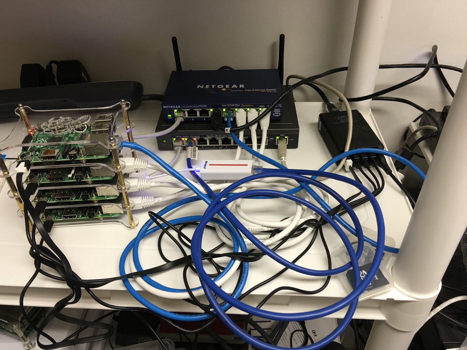
I just added a Raspberry Pi Cluster (4 RPis) to experiment with BGP and IPSec VPNs. My thought was to have a No-Mans Land VLAN running through the house in which I could tap into with the cluster. Since the NML vlan traffic wouldn't touch any of the other vlans it would make it easy to try out different types of routing protocols. I could also use one of the RPis to act as an IPSec VPN server to connect from the outside to the NML vlan. I could set it up so that it might be on a DMZ or other path. I am therefore not constrained even though I have double routers in my network. The cluster can be seen in this picture taken this morning:

When I was putting this together I was running some tests on a bench with the following layout:

I moved the cluster and router (acting as an 8 port managed switch) to an area where I have a UPS so that the power would be filtered. The first item on the list is to get a reasonable IPSec VPN running, hopefully using StrongSwan with some decent encryption, say AES256. Since the router has a WAN port, I can use that any time that I need to update the RPis in the cluster - just add a wire and then take it away. I did discover one issue though, I am going to have to remove the Mac Mini from the NML vlan because I noticed that all of the ports that were open on my personal vlan were open on the NML vlan. I don't know how to correct that so for now, after I get the IPSec VPN setup, I will remove the Mac Mini so I can reduce the probability that someone will hack into my network.

When I was putting this together I was running some tests on a bench with the following layout:
I moved the cluster and router (acting as an 8 port managed switch) to an area where I have a UPS so that the power would be filtered. The first item on the list is to get a reasonable IPSec VPN running, hopefully using StrongSwan with some decent encryption, say AES256. Since the router has a WAN port, I can use that any time that I need to update the RPis in the cluster - just add a wire and then take it away. I did discover one issue though, I am going to have to remove the Mac Mini from the NML vlan because I noticed that all of the ports that were open on my personal vlan were open on the NML vlan. I don't know how to correct that so for now, after I get the IPSec VPN setup, I will remove the Mac Mini so I can reduce the probability that someone will hack into my network.
Saturday, January 23, 2016
TravelRouter#2 - Updated to Routed Client Mode using LuCI
I was pretty pleased with how easy it was to put the GL.iNet 6416a into a Routed Client Mode using LuCI (generic instructions are here). The basic connection was through an Ethernet cable from my laptop to the router plugged into the LAN port. The full-up connection is shown in the image:

In the expedience of time I will explain the process in the following paragraphs.
(1) connect the router via an Ethernet plugged into the LAN port and the other end placed into a USB to Ethernet adapter on the laptop.
(2) disconnect the laptop from all Ethernet connections except for the router connection.
(3) log into the router with credentials using your browser; select Network -> WiFi.
(4) click on the Scan button next to the "Generic MAC80211 802.11bgn (radio0)" line. Select the WiFi network that you wish to join by clicking on the "Join Network" button.
(5) leave "Replace Wireless Configuration" checked, this will ensure that everything is replaced. Enter the wpa2 passphrase. Make sure that WAN is selected; this will ensure that the wireless setup is associated with the WAN connection on the router. Select save.
(6) When the next screen comes up, make sure that WAN is selected. Click on Save and Apply.
(7) At the next screen you should see the selected WiFi under the "Generic..." line. Next, click on the Add button next to the "Generic..." line. Select LAN to associate with this new WiFi SSID. Change the name from"OpenWRT" if you desire a different SSID for your LAN network connection.
(8) select Wireless Security tab to setup the WPA2 data. Select WPA2-PSK for encryption and "Force TKIP and CCMP (AES)" from the dropdown next to Cipher. Add the passphrase as necessary. Click on Save and Apply. This will bring you back to the screen with the "Generic..." line. You should see both the SSID of the WiFi you are connected to on the WAN side, and the SSID for the LAN side. At this point you are set up.
That is pretty easy setup for OpenWRT. Next, I got to figure out a couple of different setups including one with OpenVPN back to my house.
Friday, January 15, 2016
TravelRouter #1 - I Bought a GL-iNet 6426A Travel Router
After some looking around, I ended up buying a GL-iNet 6416A Travel Router from Amazon for $24. What intrigued me about this router was the (1) OpenWRT based system and (2) the ability to reflash it with a new version of OpenWRT if I wanted. So the first thing that I did after getting the router was to reflash it (instructions here) with the latest Chaos Calmer version. This eliminated the tweeks that the company had placed on the router, but I wanted to customize my own. BTW, the company provided a very nice suite of abilities for the novice. This router was also the basis for the nefarious TOR routers that showed up on kickstarter a couple of years ago. Those routers were tossed because they claimed original prototypes and manufacturing when in fact they were just repackaging the GL-iNet 6416A. The following is an image of the router from rednerd.com (his site has a very good description of how to add TOR to this router).

I also immediately set the system to allow ssh connections on the LAN side. The next tweek was to update the software listings and setup LuCI for web interface. I did that through ssh (instructions here). I next setup the router with my own SSID and WPA2 password (without enabling the wireless). The interface allowed me to choose between putting the wireless on the LAN or the WAN side of things, I chose LAN. After all that, it would appear that I have about 11.95 MB more space for software. That means that I can do a lot with it.
My main thought is to setup some standard configurations with some kind of selection through the web interface to easily set the router to what I want. That may take some doing. More Later.
Monday, January 11, 2016
Cluster#1 - 802.1q at L2 Along with Routing at L3 in the 1-Port Router
Ok, I am still playing around here with routing and 802.1q. My latest endeavor is using Quagga along with shorewall to produce some useful home appliances. Unfortunately, this is all going to be running at a 100MHz clip on Ethernet rather than the nice 1GHz Ethernet lines I have running through the house. However, I get to play with the outcome.
When I last broached the subject here, I had added the 802.1q capability to the RPi Raspbian load. I have since been adding a number of RPis, without a clear purpose to what I would do with them. I now have a quad RPi cluster (shown in the image above) that I can use for some of the networking experiments. The latest experiment is to setup each RPi in the cluster with a Quagga and shorewall routing load. Shorewall is primarily a firewall, but with some alterations to the definition files, it will serve its purpose as a router capability. The Quagga software allows me to experiment with OSPF and BGP routing protocols, the idea being that I can simply configure them and drop them into my network at home at any place and the routing tables will automatically be built for me.
My idea is to use the normal Ethernet interface to the RPi as the connection point to the other Quagga/shorewall RPis on a separate no-mans land VLAN. I would then use 802.1q to trunk my way into VLAN switches which would then distribute the information as necessary. I can also modify the way that I am connecting and actually have a VLAN switch capability on an RPi with attached USB hub running to USB-to-Ethernet adapters, each "port" having a trunk line or untagged port. This of course gets somewhat expensive since the cheapest I can find those adapters is $6.99 at amazon. I wish that I could find an Ethernet switch adapter that would allow me to experiment with an RPi controller.
Update: as you can see from the new site picture, I have been able to setup the RPi cluster along with some cheap ($6.99) USB to Ethernet adapters. Now the fun begins!
Subscribe to:
Posts (Atom)