So this project has been on the back burner for some time. I never got the hardware over to something besides a breadboard, and I did not have the software running in the RPi0W. I have a three day weekend coming up and I thought I might revive it and get it working with the Home-Assistant setup in my house. I am trying to at least get the interface to my car working with the lights on the porch using this setup. At this point I am thinking my best bet will be to load docker into the raspberry pi zero w and spin up a container of nodered to interface with the RPi0W and to send out packets to my MQTT server when buttons are pressed on my Subaru rear view mirror. I decided to use an 8GB micro SD for this project since not much will change.
1. First things first - install Buster using the Win32DiskImager (see Stupid RPi Tip #5)
2. Next update the OS (Buster went from test to stable, so have to use apt instead of apt-get first)
sudo apt update
sudo apt-get upgrade
3. Next install docker
curl -sSL https://get.docker.com | sh
4. now that we have docker installed, need to get a working version of nodered in a docker container; also, it might be nice to have Portainer running to check status; we will use docker-compose for this (I usually set everything up in a directory in /srv/docker/); docker-compose.yml file is as follows:
version: '3'
services:
portainer:
container_name: portainer
image: portainer/portainer
volumes:
- /srv/docker/portainer:/data
- /var/run/docker.sock:/var/run/docker.sock
ports:
- "9000:9000"
nodered1:
container_name: node-red-1
restart: unless-stopped
image: nodered/node-red-docker
user: root
volumes:
- /srv/docker/node-red-1/user:/data
- /etc/localtime:/etc/localtime:ro
ports:
- "1880:1880"
Prior to launching DockerCompose we need to have a directory /srv/docker/node-red-1/ and /srv/docker/portainer/ ready to go.
mkdir /srv/docker/portainer
mkdir /srv/docker/node-red-1
Now put the docker-compose.yml file into /srv/docker/ directory. Next launch DockerCompose
DockerCompose up
This should get us started with node-red running in the container
To Be Continued ...

This is a blog mostly about techie things, what I am doing to my apartment network on the cheap, IOT, 3D Printing, Raspberry Pis, Arduinos, ESP32, ESP8266, Home Automation, Personal Weather Stations, Things That Go Bump in the Night, and some side issues that need discussing. Remember, sometimes the journey to an end is as much fun as the goal achieved!
Thursday, September 5, 2019
HomeLink HA Interface #5 - Ooops!
I decided to get back into putting the interface together and finishing out the prototype. I also decided to pull it apart from the breadboard and put the hardware onto an Adafruit perma-proto board that would interface directly to the RPi0W. Little did I know that I would make a strategic mistake.
First of all, I pulled up Fritzing and put the wiring up on the board (visually) as shown:
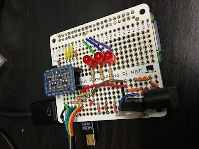
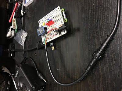
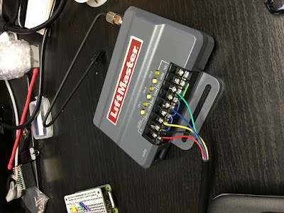
As shown, I added three red LEDs to be able to pulse as a visual reference when the HomeLink channel is selected. I also place a 7805 power tab in the lower right hand corner of the board. If the board looks weird it's because it is the size normally used for a regular sized RPi. And yes, it does overhang. The 5 lines are actually a cable that goes from the breadboard to the LiftMaster. These can be seen in the following images:


The Ooops in the title stems from the fact that when I applied power (9v to the breadboard connector) I encountered the following:
What I have since surmised is that the peripherals that I had plugged into the RPi0W were drawing way more than the 1 amp max the 7805 could handle. So what I plan on doing is removing the 7805 and replacing it with a 5v 2.5a supply that plugs into the RPi0W connected with a step up converter to push 9v to the LiftMaster which only draws 40ma.
First of all, I pulled up Fritzing and put the wiring up on the board (visually) as shown:
As shown, I added three red LEDs to be able to pulse as a visual reference when the HomeLink channel is selected. I also place a 7805 power tab in the lower right hand corner of the board. If the board looks weird it's because it is the size normally used for a regular sized RPi. And yes, it does overhang. The 5 lines are actually a cable that goes from the breadboard to the LiftMaster. These can be seen in the following images:


The Ooops in the title stems from the fact that when I applied power (9v to the breadboard connector) I encountered the following:
- while the RPi0W was booting, I tried out the clicker with the LiftMaster and it was working fine
- the bootup of the RPi0W seemed to be going fine, then it rebooted, and then rebooted, etc.
- I reached over to turn off the monitor I was using and burned my finger on the 7805 poking up from the breakboard
- I went and got my temperature laser reader and when I rebooted the RPi0W I was reading in short order about 150 degrees Fahrenheit. Way too much current was being drawn.
What I have since surmised is that the peripherals that I had plugged into the RPi0W were drawing way more than the 1 amp max the 7805 could handle. So what I plan on doing is removing the 7805 and replacing it with a 5v 2.5a supply that plugs into the RPi0W connected with a step up converter to push 9v to the LiftMaster which only draws 40ma.
Sunday, September 1, 2019
Project #16 - Add a DNS-DHCP-Radius Server for use Across the Network
It seems like a good idea to add a single place where I can get DNS, DHCP, and provide a Radius Server for authentication of the Routers and Switches.
Labels:
DHCP,
DNS,
OBE Project,
Radius
Subscribe to:
Comments (Atom)
