Labels

Showing posts with label Network. Show all posts

Sunday, January 25, 2026

IP Power Strip #03 - the Python development environment setup for the IP Power Strip

I have been reviewing some blog material concerning Python docker development, here, here, and here.  In addition I have been reviewing some Python libraries developed to interface with MQTT.  I intend to use docker-compose to separate out the different elements so that I can individually change the code.  I also need to think closely about how I will be developing containers that might run on different platforms other than the Raspberry Pi, for instance on the Ubuntu server which is of a different architecture.  The environment should look like this:

  • IP_Power_Strip_Project
    • docker-compose.yaml
    • Master
      • Dockerfile
      • requirements.txt
      • Src
        • globals.py
        • Master.py
    • Slave
      • Dockerfile
      • requirements.txt
      • Src
        • globals.py
        • Slave.py
    • InterfaceProxy
      • Dockerfile
      • requirements.txt
      • Src
        • globals.py
        • InterfaceProxy.py
    • Shutdown
      • Dockerfile
      • requirements.txt
      • Src
        • globals.py
        • Shutdown.py

For right now that covers it.  I will update this post as I come into other aspects of the development.

UPDATE: rejuvinated

IP Power Strip #02 - How the IP Power Strip will work in the network

I am looking to make the IP Power Strip as useful in my network as is possible.  I should be able to use the IP Power Strip outside of the normal turn on/off my HomeLab and extend it to things like control lights during Christmas and Halloween.  What I am doing is turning power on and off.  Throughout the year it makes sense that I would use the units in the HomeLab, but these units would also have a use elsewhere.  I am rather interested in integrating it with my HA-IOT network and use the MQTT server that already resides there.

For the Master container, I visualize the following:

  • it should be able to be "programmed" with control sequences to a certain point through MQTT messages
  • I should be able to issue different sets of controller sequences "programs" so that the IP Power Strip can be controlled independently depending on the context
  • I should be able to issue a list of IP Power Strip containers (IP addresses) to the Master container so that it knows the locations
  • I should be able to effect a controlled sequence when tasked by an MQTT message
  • I should be able to simply indicate a vacation mode and have the Master container do the rest
  • I should be able to poll the Master container to reveal the current status of the IP Power Strips and what they are controlling
  • The Master container should be able to respond to heartbeat messages in context

For the Slave container, I visualize the following:

  • I should be able to have the Slave container come up issuing heartbeat messages to the Master container to indicate the status
  • The slave container should be able to be controlled via MQTT messages for a single change or multiple changes
  • The slave container should be able to be controlled via MQTT messages to stop/start issuing heartbeat messages

For the InterfaceProxy container, I visualize the following:

  • This container is how we interface to the actual equipment, it is a proxy by reason that there may be other already built IP Power Strips, or power like systems that we want to integrate into the IP Power Strip system
  • The InterfaceProxy container should be controlled by a RESTful interface, with json coding
  • The only container that would interface would be the Slave container, on the other side is hardware
  • The InterfaceProxy should receive unique IDs and be able to respond to a request for number of "ports" as well as initial setup and current setup for the "ports".  Initial setup defines how the "ports" come up from a hot start
  • Notice that the InterfaceProxy can also serve as a test container which can be metered and check for correct sequences at the low end

For the Shutdown container, I visualize the following:

  • I should be able to have the Shutdown container come up issuing heartbeat messages to the Master container to indicate the status
  • The Shutdown container should be able to be controlled via MQTT messages to start a shutdown on the computer where it resides
  • The Shutdown container should be able to be controlled via MQTT messages to stop/start issuing heartbeat messages

UPDATE: rejuvinated

Saturday, April 6, 2024

State of the Network - April 2024

Lately I have been working some electronics projects, genealogy, and really haven’t had time to really work on my HomeLab.  Sensing that I haven’t posted for some time I thought I might post about the HomeLabs current condition.  While I am working on the electronics projects most of the equipment is turned off.  In fact, I normally have only the Edgerouter-12 and the Netgear M4100-26g turned on since my laptop is pretty much permanently connected to the Server Admin vlan. So here are some bullit points  to explain where the HomeLab sits:
  • I now have a managed switch at the top of the rack to connect to the outside (powered on with the rack)
  • I have pushed the two Edgerouter-X routers and one managed switch into the back of the rack with their ports coming out to the front
  • I now have a 24 port patch panel that connects to some ports on the top 24 port patch panel, the two ER-Xs, the managed switch, and to the 5 input ports on the Proxmox server
  • I can now power the xPod, Monitor Network, Proxmox server, some specific rack RPis, and the ER-12/M4100-26g separately
  • The external managed switch behind the rack has been wired differently to accomodate the changes and additional experiments on the HomeLab table
  • I now have two LED strips on the front of the rack to illuminate the patch wiring
  • I also have two LED strips under my laptop holder on the HomeLab table to illuminate electronic circuits on the table
  • I have incorporated an UAP-AC-AD to output four specific vlan connections; one of which goes to my development vlan
These are items that I have changed but I still have items that I haven’t implemented yet. My thoughts about what I want keep changing as I come up with other ideas.  So here are some future items that I want to implement:
  • I recently obtained an Edgerouter-12P which will provide POE capability in the rack and beyond; I need to determine how I will use it
  • I also obtained a couple of UAP-AP-LR WAPs which I hope to use to form a wi-fi link to the back bedroom (I am unable to get an Ethernet cable pulled from the living room to my back bedroom) because the Power adapters only give me 130 Mbps throughput.
  • I hope to spin up two RPi Zero Ws at opposite ends of the Ethernet over power link to monitor failures
  • I hope to spin up a RPi 4B in the living room as a PiHole to be the definition of connections within my network
  • I hope to be able to use my SLATE router, connected to a 2.4 GHz wi-fi connection as a fall over from the FLINT router
  • I also hope to figure out how to integrate Midi into my HomeLab including a new Zynthian Synthisizer on an RPi 3B+

Friday, June 19, 2020

Tips #3 - Documentation on Networks and Vlans

As your home network grows, so does the level of confusion about what was wired up where and when.  In general, you can document what happened through a journal about changes you have made to the network.  But filtering through that journal when you are in the midst of making lots of changes will be very time consuming.  It is better to keep the information in a separate list.  Normally, devices that you have in the network will retain certain Ethernet addresses, but sometimes the wiring will change and the placement of the equipment as well.  There are four specific documents that I use to document different views of the network and provide an easier way of changing the layout as my equipment, equipment placement, wiring, etc. change over time.  In my case, I keep the four documents as notes in my CellPhone under a classification of HomeNetwork.  The four documents are:
  1. Current IPs in the Network
  2. Patch Panels
  3. Cable Connections
  4. Home Vlans
These are described below:

-- Current IPs in the Network
  • The "Current IPs in the Network" and "Home Vlans" rarely if ever change.  However, if I move a piece of equipment in my network, "Patch Panels" and "Cable Connections" will be altered.  If I move a piece of equipment from one vlan to another, by definition the "Current IPs in the Network" will change, along with notations about the connections in the other documents.
  • The "Current IPs in the Network" note should contain all known IPs that you have in your home network.  I have even included IPs from equipment that are connected to multiple vlans.  That way the document is all inclusive.  I also make sure that all IPs that show up in my network are known.  If it isn't on the list then I know someone has attached themselves to my network that I don't know about and I go and hunt down what it is.  Rogue pieces of equipment or IOT equipment that doesn't behave I disconnect.
-- Patch Panels
  • I have already described how I label patch panels here.
  • The "Patch Panels" note documents the infrastructure of the network
  • The "Patch Panels" note is broken down to each patch panel with what is connected by port number on that patch panel.
  • The "Patch Panels" not does not contain any information about what equipment the port connects to, i.e. with a patch cable connection from the device to the patch panel, only documentation of what connections exist.  
  • There is an exception where the patch panel port actually goes directly to a device and is designed to be there consistently.  For instance, I have a PiHole in my network and that is connected behind one of my patch panels.  So for the label on that patch panel, I label the port as "PiHole", e.g. PP#3-7 is labeled PiHole so I know where the port goes to.
  • I use the term "patch to" when describing the use of a patch cable at a specific patch panel.  For instance one of my patch designations at patch panel 3 port 11 is "PP#3-11 - PP#1-10".  I can usually read where the port is going by looking at the actual patch panel.
  • If I have a patch cable going between ports on a given patch panel, my "Patch Panels" note will have something like this: "PP#1-10 - PP#3-11 (patch to PP#1-9)" for the designation on patch panel one port 10, and I will have "PP#1-9 - PP#2-6 (patch to PP#1-10)" for patch panel one port 9.  Note that this shows where my patch cables are and how they connect.  I can always go to the "Patch Panels" note and trace from one point to another to understand where the cable ends.
  • If I move/remove the patch cable from a patch panel, then I can simply modify a couple of lines to show how things are connected.  Again, the idea is to be able to trace to the end.
  • Note that I do not list any patch cables from devices that are plugged into a port on one end or the other.
-- Cable Connections
  • The "Cable Connections" note is where I list the patch cable connections to devices.  It also designates a logical connection to an end point.  Normally there would be a patch cable from a device, and on the other end of the trace there would be a connection to a different device.
  • The "Cable Connections" note is grouped by device which allows me to immediately find out where the device is connected by port number.
  • In the "Cable Connections" note I describe on a device port where the connection ends up.  For instance, I have a connection from my main switch which is a "trunk" connection to another switch.  The way that I write it is as follows, using the last portion of the switch IP addresses:  ".119-15 - to PP#3-23 -> .118-1 [6/T]" which is a shorthand way of listing where the connection ends up, even though the actual trace through my network goes through 3 patch panels.  I can trace the physical connections through the "Patch Panels" listing and I note the vlan trunk elements (a tip on vlan nomenclature is here).  Correspondingly, I look at the port for the receiving switch and it looks like this: ".118-1 - to PP#4-X -> .119-15 [6/T]" which indicates the reverse direction.  Again, I can look through the "Patch Panels" listing and discover the physical connections through my network.
-- Home Vlans

  • The "Home Vlans" note is where I give a listing of each vlan used in my network, including why I have the vlan, what DHCP server address is used, and what DNS server address(s) are used.
  • The "Home Vlans" note also contains a line which lists the trunk line vlans for the normal case.


Thursday, June 18, 2020

Tips #2 - Network Journal

Having been an engineer for the last 45 years, I do keep track of what I do in my network.  This includes how I wire up things and why, what I do with equipment, things that I am thinking of doing, future projects, documenting current projects, and software changes.  I use a manually maintained engineering notebook format to do this.  In my case, I call it a Network Journal.  I use the following format (based on the principle of linked lists and indexes) when documenting stuff in the Network Journal (it just works for me):

  1. I always use quad ruled composition books for my notebooks.  The quad rule gives something for the eye to use when drawing diagrams.
  2. Each page in the notebook needs to have a number starting from 0.  The page numbers provide an easy reference point when indexing.
  3. Page 0 is reserved for a Table of Contents.
  4. The title of the notebook in our case is "Network Journal".  In general, I title each notebook with the subject that the notebook contains.  If this is the second notebook in the subject, it would be titled "Network Journal 2".  Write it in ink.
  5. The notebook should be individually numbered, I like to use an abbreviation of the subject, in caps, with a dash and a number.  In this case the number of the notebook would be "NETJRN-1" with "NETJRN-2" for the second notebook in the subject.  It should be written on the front of the notebook and also written across the bottom of the notebook (there should be enough space to write this when holding the pages together.  The purpose is to be able to see the number if the notebook is laid down or is stored vertically in a page sorter used for storing multiple notebooks on different subjects.
  6. The rule when referencing page numbers is that if it is in the same notebook you use the page number alone.  If it references a page in a different notebook you reference the notebook number a slash and the page number in that notebook.  If I reference page 53 in the same notebook, it is "->53".  However, if I reference page 87 in a different notebook, say "NETJRN-1" then I use "->87/NETJRN-1".  In this manner I can reference things in all of my notebooks from each other.
  7. One specific rule is that I never erase a page in a notebook.  I keep it for posterity, including references.
  8. When I put an index on a page, I title the index drawn on a line about 3/4 of an inch below the top.  I underline the title, and put the date that I started the index in the margin to the left.  If this index is a continuation of an index, I use the same title, but reference the page that has the previous index by a back arrow ("<-page_number") with a box around it.  If this index is a lower hierarchy from the previous index, I use an up arrow curving left ("<-|page_number") to reference the page.   Note that if I continue the index to a different page, I use an arrow pointing to the page and draw a box around it - "->page_number".
  9. An item to me is an individual thing that I wish to keep track of by referencing it from an index.  This could be meeting minutes if I discuss something with someone, an idea that I want to expand upon, a specific change that I am making to cabling, a new vlan and a description of its purpose, etc.  This includes text, drawings, portions of pages that have been scanned.  Each item has a title and that title should be on the same page
  10. When I add an item to an index page, I put the title that I have used on the page in the notebook, put the date in the left hand column, and on the same line I point to the page that the item occurs on "->page_number".  This way I can simply look down the page and go right to the page number of the item I am interested in reviewing.
  11. Likewise when items go on a page, if this is the first thing on the page - I put the topic of the index that this page refers to at the very top of the page (if it is not there already).  Note, I limit it to one index topic per page to ensure that everything on the page is of the same index topic.  If there is already some items on the page for the same topic, I draw a line across and continue after the line on the same page.  I start with the title underlined, with the date in the left hand margin, then I put an up arrow curving left ("<-|page_number") with the page of the index that refers to this item.
  12. If I need to continue the item on a different page, I just put an arrow pointing to the page I am continuing on and form a box around it ("->page_number").  Then I repeat on the new page.  Note that I don't have to use the very next page, I can even go backwards if necessary.


Monday, July 22, 2019

Setting up a Certificate Authority on the RPi

One of the things that I have determined that I need in my system is the ability to create security certificates, especially X.509 certs.  I don't want to have to spend money for certifications that I will only be using internally to my network or in connecting to my network.  I can do this by setting up my own Certificate Authority (CA).  A CA is used to create and sign certificates as being authenticate.  Since I am in a controlled environment I can make sure that these certificates are specific to my needs and since I will not be releasing the public CA certificate, will allow me to control access to my network.

I can use the CA to sign certificates to be used with: my internal network connections, openVPN, and IPSec connections from the outside.  In addition, I need to setup a simplified way of creating symetric encryption certificates.  I will only have the CA open long enough to do what I need to do and then I will shut it down and remove it from my network - so it will remain secure from attack from the outside.  I can also use it at work to do my certificates without being connected to a network so it is even more secure.

I used one specific article to setup my Certificate Authority at xxxxx.  I am repeating the steps here for reference purposes:

Make an SSL Certificate Authority and Associated Certificates

(1) Create the Root Key

[Mydev@xxx My_CA]$ mkdir -p MyCA/cert MyCA/key
[Mydev@xxx My_CA]$ cd MyCA
[Mydev@xxx MyCA]$ openssl genrsa -aes256 -out key/Myca.key.pem 4096
Generating RSA private key, 4096 bit long modulus
.......................................................++
....................................................................++
e is 65537 (0x10001)
Enter pass phrase for key/Myca.key.pem:
Verifying - Enter pass phrase for key/Myca.key.pem:
[Mydev@xxx MyCA]$ chmod 400 key/Myca.key.pem
[Mydev@xxx MyCA]$ 

(2) Create the Root Cert

[Mydev@xxx MyCA]$ openssl req -key key/Myca.key.pem -new -x509 -days 3650 -sha256 -extensions v3_ca -out cert/Mycert.pem
Enter pass phrase for key/Myca.key.pem:
You are about to be asked to enter information that will be incorporated
into your certificate request.
What you are about to enter is what is called a Distinguished Name or a DN.
There are quite a few fields but you can leave some blank
For some fields there will be a default value,
If you enter '.', the field will be left blank.
-----
Country Name (2 letter code) [XX]:US
State or Province Name (full name) []:MyState
Locality Name (eg, city) [Default City]:MyTown
Organization Name (eg, company) [Default Company Ltd]:HOME
Organizational Unit Name (eg, section) []:HOME
Common Name (eg, your name or your server's hostname) []:My CERT
Email Address []:myemail@myemail.com
[Mydev@xxx MyCA]$ 

Note: cert/Mycert.pem is the CA's certificate and is public - this needs to be loaded into all clients in the My network.  key/Myca.key.pem is the CA's private key - it is protected by the password MYCAKEYPASSWORD and it should be restricted access so that only root can read it.

(3) Create the First Server key/cert combo

[Mydev@xxx MyCA]$ mkdir myserver1
[Mydev@xxx MyCA]$ openssl genrsa -aes256 -out myserver1/myserver1.My.local.key 4096
Generating RSA private key, 4096 bit long modulus
.........................................................................................................++
................................................................................++
e is 65537 (0x10001)
Enter pass phrase for myserver1/myserver1.My.local.key:
Verifying - Enter pass phrase for myserver1/myserver1.My.local.key:
[Mydev@xxx MyCA]$ openssl req -new -key myserver1/myserver1.My.local.key -out myserver1/myserver1.My.local.csrEnter pass phrase for myserver1/myserver1.My.local.key:
You are about to be asked to enter information that will be incorporated
into your certificate request.
What you are about to enter is what is called a Distinguished Name or a DN.
There are quite a few fields but you can leave some blank
For some fields there will be a default value,
If you enter '.', the field will be left blank.
-----
Country Name (2 letter code) [XX]:US
State or Province Name (full name) []:MyState
Locality Name (eg, city) [Default City]:MyTown
Organization Name (eg, company) [Default Company Ltd]:HOME
Organizational Unit Name (eg, section) []:HOME
Common Name (eg, your name or your server's hostname) []:My OPERATOR CERT
Email Address []:myemail@myemail.com

Please enter the following 'extra' attributes
to be sent with your certificate request
A challenge password []:
An optional company name []:
[Mydev@xxx MyCA]$ openssl x509 -req -days 3650 -in myserver1/myserver1.My.local.csr -CA cert/Mycert.pem -CAkey key/Myca.key.pem -set_serial 01 -out myserver1/myserver1.My.local.crt
Signature ok
subject=/C=US/ST=MyState/L=MyTown/O=HOME/OU=HOME/CN=My OPERATOR CERT/emailAddress=myemail@myemail.com
Getting CA Private Key
Enter pass phrase for key/Myca.key.pem:
[Mydev@xxx MyCA]$ 

(4) Make a passwordless version of the server key

[Mydev@xxx MyCA]$ openssl rsa -in myserver1/myserver1.My.local.key -out myserver1/myserver1.My.local.key.insecure
Enter pass phrase for myserver1/myserver1.My.local.key:
writing RSA key
[Mydev@xxx MyCA]$ mv myserver1/myserver1.My.local.key myserver1/myserver1.My.local.key.secure
[Mydev@xxx MyCA]$ mv myserver1/myserver1.My.local.key.insecure myserver1/myserver1.My.local.key

Note: this passwordless key is the key that we will ultimately use so that we do not need human intervention when trying to use the certs.  Otherwise you type in the cert password everytime you restart the service.

(5) Import the CA and Cert

Note: copy the MyCA/Mycert.pem, myserver1/myserver1.My.local.key, and myserver1/myserver1.My.local.crt files to the server.  The MyCA/Mycert.pem has to be imported into the certificate store - this is the intermediate CA certificate and identifies the myserver1 certs as valid.

(6) Repeat for the Second cert

[Mydev@My-ib6-devel MyCA]$ mkdir myserver2
[Mydev@My-ib6-devel MyCA]$ openssl genrsa -aes256 -out myserver2/myserver2.My.local.key 4096
Generating RSA private key, 4096 bit long modulus
............................................................................................................................................................++
..................................++
e is 65537 (0x10001)
Enter pass phrase for myserver2/myserver2.My.local.key:
Verifying - Enter pass phrase for myserver2/myserver2.My.local.key:
[Mydev@My-ib6-devel MyCA]$ openssl req -new -key myserver2/myserver2.My.local.key -out myserver2/myserver2.My.local.csr
Enter pass phrase for myserver2/myserver2.My.local.key:
You are about to be asked to enter information that will be incorporated
into your certificate request.
What you are about to enter is what is called a Distinguished Name or a DN.
There are quite a few fields but you can leave some blank
For some fields there will be a default value,
If you enter '.', the field will be left blank.
-----
Country Name (2 letter code) [XX]:US
State or Province Name (full name) []:MyState
Locality Name (eg, city) [Default City]:MyTown 
Organization Name (eg, company) [Default Company Ltd]:HOME
Organizational Unit Name (eg, section) []:HOME
Common Name (eg, your name or your server's hostname) []:My MAINTAINER CERT
Email Address []:myemail@myemail.com

Please enter the following 'extra' attributes
to be sent with your certificate request
A challenge password []:
An optional company name []:
[Mydev@My-ib6-devel MyCA]$ openssl x509 -req -days 3650 -in myserver2/myserver2.My.local.csr -CA cert/Mycert.pem -CAkey key/Myca.key.pem -set_serial 01 -out myserver2/myserver2.My.local.crt
Signature ok
subject=/C=US/ST=MyState/L=MyTown/O=HOME/OU=HOME/CN=My MAINTAINER CERT/emailAddress=myemail@myemail.com
Getting CA Private Key
Enter pass phrase for key/Myca.key.pem:
[Mydev@My-ib6-devel MyCA]$ openssl rsa -in myserver2/myserver2.My.local.key -out myserver2/myserver2.My.local.key.insecure
Enter pass phrase for myserver2/myserver2.My.local.key:
writing RSA key
[Mydev@My-ib6-devel MyCA]$ mv myserver2/myserver2.My.local.key myserver2/myserver2.My.local.key.secure
[Mydev@My-ib6-devel MyCA]$ mv myserver2/myserver2.My.local.key.insecure myserver2/myserver2.My.local.key

(7) Repeat for the Third cert

[Mydev@My-ib6-devel MyCA]$ mkdir myserver3
[Mydev@My-ib6-devel MyCA]$ openssl genrsa -aes256 -out myserver3/myserver3.My.local.key 4096
Generating RSA private key, 4096 bit long modulus
...........................................................................................++
..........++
e is 65537 (0x10001)
Enter pass phrase for myserver3/myserver3.My.local.key:
Verifying - Enter pass phrase for myserver3/myserver3.My.local.key:
[Mydev@My-ib6-devel MyCA]$ openssl req -new -key myserver3/myserver3.My.local.key -out myserver3/myserver3.My.local.csr
Enter pass phrase for myserver3/myserver3.My.local.key:
You are about to be asked to enter information that will be incorporated
into your certificate request.
What you are about to enter is what is called a Distinguished Name or a DN.
There are quite a few fields but you can leave some blank
For some fields there will be a default value,
If you enter '.', the field will be left blank.
-----
Country Name (2 letter code) [XX]:US
State or Province Name (full name) []:MyState
Locality Name (eg, city) [Default City]:MyTown
Organization Name (eg, company) [Default Company Ltd]:HOME
Organizational Unit Name (eg, section) []:HOME
Common Name (eg, your name or your server's hostname) []:My ADMINISTRATOR CERT
Email Address []:myemail@myemail.com

Please enter the following 'extra' attributes
to be sent with your certificate request
A challenge password []:
An optional company name []:
[Mydev@My-ib6-devel MyCA]$ openssl x509 -req -days 3650 -in myserver3/myserver3.My.local.csr -CA cert/Mycert.pem -CAkey key/Myca.key.pem -set_serial 01 -out myserver3/myserver3.My.local.crt
Signature ok
subject=/C=US/ST=MyState/L=MyTown/O=HOME/OU=HOME/CN=My ADMINISTRATOR CERT/emailAddress=myemail@myemail.com
Getting CA Private Key
Enter pass phrase for key/Myca.key.pem:
[Mydev@My-ib6-devel MyCA]$ openssl rsa -in myserver3/myserver3.My.local.key -out myserver3/myserver3.My.local.key.insecure 
Enter pass phrase for myserver3/myserver3.My.local.key:
writing RSA key
[Mydev@My-ib6-devel MyCA]$ mv myserver3/myserver3.My.local.key myserver3/myserver3.My.local.key.secure
[Mydev@My-ib6-devel MyCA]$ mv myserver3/myserver3.My.local.key.insecure myserver3/myserver3.My.local.key

Thursday, June 20, 2019

Network General - added an EdgeRouter X as an OpenVPN server

I had attempted to use one of the GL-iNet routers (AR800M) to act as an OpenVPN server on my network.  I setup one of the vlans from the Main Router and had a whole lot of problems with the setup.  I discovered that the EdgeRouter-X (ER-X) was only $65 from MicroCenter and a lot of people indicated that is was an easy setup for OpenVPN.  I decided that what I would do was setup a vlan from the Cisco router with one of my unused vlans that flows throughout the network.  So I designated one of my many vlans to be an “OpenVPN passthrough”.  This will be similar in concept to the No-Mans Land vlan that I have been using for some time.  The “OpenVPN passthrough” vlan will be setup so that you cannot change the Cisco router and you cannot access any other vlan.  I will also punch some ports through the Cisco router to the Wan port of the ER-X.  The OpenVPN setup is shown at https://help.ui.com/hc/en-us/articles/115015971688-EdgeRouter-OpenVPN-Server.  I have found this to be a very easy setup.  I also generated some additional OpenVPN client cents to use with my cell phones, iPads, and laptops.

Sunday, May 13, 2018

OVS Changes #2 - getting Docker containers to attach to the OVS bridges

Now that I have been successful with KVM VMs and their connections to the OVS bridges, I need to figure out how to do much of the same thing with Docker containers.  One of the reasons that I run ubuntuServer is because it is very easy (so they say) to get Docker containers running.  So now, what I am going to attempt is to startup a Docker container attached to one of the OVS bridges, used on a pfSense KVM VM.

So according to the site, http://containertutorials.com/network/ovs_docker.html, I have to do the following steps:

Install OVS (already done on my system) -

Install OVS-docker utility (already done on my system) -

Create an OVS bridge (already done on my system, except the bridge doesn't have an IP address) -

Create the docker container

Connect the container to the OVS bridge, such as
$ ovs-docker add-port ovs-br1 eth1 <container_name> --ipaddress=<ip_address_for_container>

OVS Changes #1 - Updating the ubuntuServer to use OVS bridges

One of the things that I wanted to do with my network was to be able to access multiple vlans while I was away on trips or from the office.  I hit upon the use of OpenVSwitch (OVS) as a means of connecting an Ubuntu VM running under VMWare on my Windows 10 laptop.  In addition, I wanted to be able to run a set of Docker containers from my Mac Mini server and have them connected to the ubuntuServer.  So, in effect I have a SDN within my house that can be connected to through my VPN server.

I had setup bridges to multiple Ethernet ports using the following template:


iface <ethernet-port-name> inet manual

auto <bridge-name>
iface <bridge-name> inet manual
        bridge_ports <ethernet-port-name>

The setup is in a number of bridge definition files located in /etc/network/interfaces.d/; one file per interface.  The only template that is in /etc/network/interfaces is the one that I have for my day-to-day network activities.  Again, I separate out vlans for different purposes making sure that the vlans do not talk to each other except in controlled instances.

What I did to use an OVS generated bridge was to remove the bridge definition file from /etc/network/interfaces.d/ and then delete the previous bridge using:


sudo ip link set <bridge-name> down
sudo brctl delbr <bridge-name>

sudo brctl show

and then perform the following command (note the ovs addition to differentiate it):

sudo ovs-vsctl add-br <bridge-name-ovs>
sudo ovs-vsctl add-port <bridge-name-ovs> <ethernet-port-name>
sudo ovs-vsctl show

Which is done for each port that I have defined, except for the day-to-day port.  It turns out that you can use the Virtual Machine Manager to pull up the VM, reset the bridge designations from the pull-down list, hit apply, then launch the VM.  Works very well with pfSense.  The interesting thing is that the <bridge-name-ovs> will now show up in an ifconfig command, where as before (when first created with OVS) would not.  Also, there are now tap devices that show up in ifconfig, like macvtap0 and macvtap1.  Those correspond to the tap device attached to the KVM VM; created from the use of Virtual Machine Manager.  I still need to figure out how to do this with Docker.

Anyway it works!  I am able to pull up the VMs on the correct vlan now.

Thursday, December 21, 2017

LED - Light Controller #1 - Introduction and Idea

I have been thinking about next Christmas season and I have decided to get my act together and put together a LED Strip Controller Helix and Light Switching Box.  I want it to be RPi/Arduino controlled and interfaced to my home network.

The requirements for Light Switching Box are as follows:
  1. Circuit A and B, with inputs A and B from mains
  2. 8 individually switched circuits - one socket per
  3. Main switch toggles off, circuit A or circuit A+B - real switch
  4. Fuses on incoming?
  5. One socket always connected to circuit A for RPi, always powered when A is plugged in
  6. Connection to RPi through I2C, 16 port ic through level shift
  7. 8 ports used for 8-port relay, remaining 8 ports for switch and led functions?
  8. RGB led for boot up/armed function, RGB led for other indication
  9. Triple LED strip controller PCM (WS2812B)
The requirements for the LED Strip Controller Helix are as follows:

  1. Base the light on a helical strip wrapped around a 4 inch pvc pipe.  I can get about 4.5 inches in between each coil on a four foot section and make use of the controls in each
  2. Cap the top so that water cant get in
  3. Place an Arduino and power supply, for the LED strip, inside the pipe to keep it out of the weather.  If the Arduino can be controlled wirelessly, I can communicate with it to send update commands with my home network.
  4. Four wire line (for power and i2c data/clock) in the case of a non wirelessly controlled Arduino or, a Two wire line (for power) in the case of a wirelessly controlled Arduino controller.  Power only going into the box is obviously preferred.
  5. Communicate from the Light Switching Box to each Helix to relay commands and synchronize the light show.

Sunday, September 17, 2017

Checking Power for the Computer Room

So today I am checking the power coming to my new computer room.  I have cleared out most of the things that were in the room, enough to be able to get around and move my equipment into the room.  There were two lines that I uncovered coming from the main panel that went into the tool room.  One went to two outlets through a breakout box: power for the main managed switch and a 4 socket setup on the workbench.  Since I will not be using the workbench much after I move the 3D printer into the computer room, I should be okay with the power draw.  The line is on a 20 amp circuit and the switch does not draw that much.  Having the 3D printer in the computer room allows me to setup an exhaust outlet for when I start doing stinky plastics like ABS, nylon, and PETG.  The other line coming from the main panel goes to a breakout box that is tied to power going into the computer room.  I need to trace down the wires to make sure that I understand where they are going to.  I am hoping that there is not a lot of activity on this power line.

I have been looking for a power meter that I can use to determine what the current draw is on each of these lines so that I can make sure not to exceed 80%.  That should keep the lines cool enough for continuous usage.  I went to Loews last night and got some 12 gauge power wire to hook the first line I mentioned to some of the other outlets in the room.  I need to determine what the power requirements are for the following groupings of equipment:

1. Computer Rack
- 1500 watt APC
- Server One - generic PC with 7 Ethernet ports
- Server Two (future buy) - probably a NUC device
- Raspberry Pi Cluster: 4 RPis, plus 6 usb connector power supply
- 16 port 1GB managed switch
- 8 port 1GB managed switch
- 8 port 1GB switch
- Two WD myCloud devices (4TB and 3TB) plus One backup usb drive (4TB)

2. Hutch
- Smaller APC unit
- Mac Mini
- Two monitors: one with dual HDMI inputs
- powered speakers
- PC laptop docking station
- external 4TB drive
- external DVD burner
- old 3in1 printer for scanning
- Apple TV 3/Roku
- 8 port 1GB managed switch

3. DIY Electronics Table
- Smaller APC unit
- 8 port POE switch
- 8 port 1GB managed switch
- 4-unit HDMI switch
- PC power supply for bench
- One monitor w/attached RPi
- 6 usb connector power supply for RPis/Arduinos
- RPi with 7" LCD screen for monitoring

4. 3D Printer (in Lack table enclosure)
- 3D printer
- OctoPi setup with camera
- power supply for OctoPi
- Ethernet connection from OctoPi to the Hutch managed switch

Wednesday, September 13, 2017

Alterations, Alterations in the Network!

Well I'm back after a long hiatus.  I was consumed with some Security Engineering projects at work and it pretty much took all of my time.  Now I can come back to this network and continue on with my projects.  However, I have a wrinkle in the matrix - I now have to consolidate a lot of my equipment into a space that is much smaller than what I originally had available.  Fortunately, having the layout that I had through the judicious use of vlans and vlan switches, the logical movement is not going to be that complicated.

My big problem with the move is getting rid of things that were in the area that I will be moving into and consolidating the things in other areas that will be necessary to continue this HomeLab project of mine.  I am vacating a room that will shortly be made into a bedroom for the potential of having either my granddaughter or my grandson and wife stay with us.  I am all for that, and it won't happen for another year, giving me time to accomplish what I need.  I am just a hop skip and jump away from retirement anyway.  But now I have to figure on not only my servers, but my main computer in my Personal vlan, and my desk where I piddle with Raspberry Pis and Arduinos.  I also have a new hobby of 3D printing which I will be adding to the HomeLab through an OctoPi interface.  Now I have to deal with lack of power for all these devices in that one room.  I also have to think of possible future inclusions such as servers and whatnots.  I will have to run one or two Ethernet cables to support the move, but that is the least of my problems.  Fortunately, I also have enough APC devices to power up everything.

I have decided that three areas should be enough to do what I want.  I am moving my RPi Cluster and Server/NAS to a shelf unit which was already in place in the room.  I will deposit my main computer that is behind the second firewall into the hutch.  I will then bring the table that I have been using for the main computer into the room and place it where I can do experiments with electronics and small computers.  I am also thinking that I need to setup a terminal at the desk to connect to RPis and computers with VNC over SSH and RPN over SSH.  Seems like I will need to setup a localized certificate authority for everything.  I really have grown to the point that I do not trust anything anymore in terms of moving information across a network, even if it is my own network.

I don't really want to buy any more equipment so I am going to repurpose one or two switches to fit into the network.  I do need to clean up the switches to not reference vlans that are not being used.  In addition, I have to be careful to keep an administrative vlan going between major systems.

Saturday, September 3, 2016

Setting up DHCP, NTP, DNS, Radius, and LDAP on a Raspberry Pi

I have been a little bit busy lately and have not had a chance to get back to the RPi things that this blog is all about.  Part of that time was learning some things on my new 3D Printer, but that is for another blog post because it will come to play in the future.

I decided that I wanted to setup a simplified server for use on a given vlan and/or a use-case in which I need these services and do not want to rely on a router.  So I will need the following services:

  • DHCP - gives out IP addresses for the subnet that it is connected to
  • NTP - provides a time service for the subnet
  • DNS - provides a localized domain name service for the subnet
  • Radius - provides Authentication and Authorization for the subnet, specifically for switches and wireless access points
  • LDAP - provides directory services for the Radius server to maintain username/password combinations, allowed MAC addresses, ranges for subnet addresses
  • Webmin - provides a web based server update process

Seems like a tall order but it is just setting up things in an orderly manner.

Thursday, July 14, 2016

Bringing Back the 1-Port Router

Ok, now I need to set up a Raspberry Pi 1-Port Router.  I know how to accomplish this (see the article here), I just have to go through the motions to implement it.  Strange - I am on SD052; I'm going to have to quit buying these things and start reusing the ones that I already have.  The setup was as follows:

sudo apt-get update
sudo apt-get upgrade
sudo apt-get install vlan shorewall

Then to get webmin setup and running, I did the following:

I added to /etc/apt/sources.list -

deb http://download.webmin.com/download/repository sarge contrib

I then got the key for the webmin repository -

sudo wget http://www.webmin.com/jcameron-key.asc
sudo apt-key add jcameron-key.asc

I then installed webmin -

sudo apt-get install perl libnet-ssleay-perl openssl libauthen-pam-perl libpam-runtime libio-pty-perl apt-show-versions python
sudo apt-get install webmin

I am going to use the 1-Port Router to connect between three different vlans, vlan4, vlan6, and vlan8.  Webmin will be used to setup the routing functions on Shorewall so that I can do the following:

  1. Have a firewall facing out towards vlan4 from vlan6; supply dhcp services to vlan4; allow only traffic from the Mac Mini to vlan4 from vlan6; and provide a one-to-one NAT ip from my WD MyCloud onto vlan4.
  2. Have a firewall facing out towards vlan8 from vlan6; supply dhcp services to vlan8; allow only traffic from the Mac Mini to vlan8 from vlan6; and provide a one-to-one NAP ip from my ubuntuServer VM cluster.


I am going to accomplish this by the following setup (TBD).

Wednesday, February 10, 2016

Cluster#2 - Setting up an IPSec VPN into the Cluster

I want to set up the cluster to provide an IPSec VPN into the No-Mans Land vlan.  From there, I intend on setting up the other three RPis to connect to various vlans throughout my network.  The following diagram shows what I intend on doing:


The RPi coming from the Internet into NoManVlan would run the IPSec VPN.  I would then be able to access the cluster from external places.  The other three RPis would then perform the function of a gateway into other vlans from there.  Quagga would still be used to setup the routing tables in each RPi with respect to the NoManVlan.

When Something Gets Complicated - Go Simple

Well I spent a decent amount of time contemplating how I was going to mount the new 24-port switch into my network.  For the life of me I couldn't figure out how to get this 17 inch box mounted in a space that was only about 12 inches wide.  Then I started looking at all of the wires that I was going to plug into the box and I discovered that most of them could be rerouted on the other side of the air duct.  On the other side of the air duct is where I have the FIOS Quantum gateway placed.  The gateway is placed on top of a wired rack so that I could put things like the HDHomeRun Prime and a USB NAS below it.


Since I am no longer using the Prime, it occurred to me that I could use the space to mount the 24-port switch.  I could reroute the Ethernet cables so that the connection point would move from in the tool room to just outside the tool room door.  This also works out well because I can now power the 24-port switch from a different outlet which is not being that utilized.  So I simplified the problem and it will only cost me an extra three Ethernet cables to connect the current setup.

I experimented over the weekend by moving the 24-port switch under the Quantum gateway and connecting the Ethernet cable from my internal router between the switch and the gateway instead of directly to the gateway.  In other words I setup a patch vlan: Ethernet wire from router to switch in one port connected to another port that had an Ethernet wire from switch to gateway.  This gives me an out in case I need to logically move the location of my router in my network.  I am starting to get the hang of this.

Monday, February 8, 2016

Rearranging the Network

I bought a TP-Link SG2424 24-port managed switch over the weekend.  This thing is quite the beast and is made for a rack mount:


I am hoping to replace the Netgear GS108T 8-port switch in the center of my network; because I am running out of ports to use.  There is absolutely nothing wrong with the GS108T, but as you can see, I have a number of cables that are not connected because of lack of ports:


I am also thinking of other types of things that I can do, like using this switch placement as a main switch point for the network since it is right outside where I have my Fios Quantum router.  The biggest problem I am facing at this moment is how to mount the 2424.  The current mounting is a simple sheet of plywood with two screws that the GS108T mounts onto.  With a rack mount size device, I am going to have to raise it further to get over the heating duct, and potentially have issues with heat and cold on the device.

Added Raspberry Pi Cluster for Experimenting

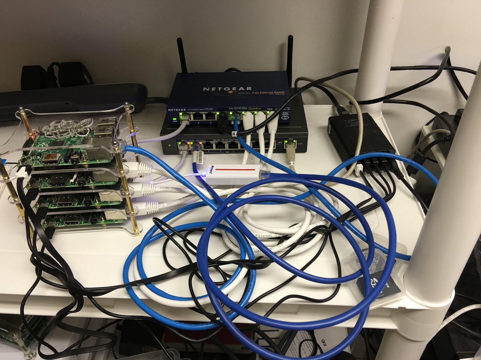
I just added a Raspberry Pi Cluster (4 RPis) to experiment with BGP and IPSec VPNs.  My thought was to have a No-Mans Land VLAN running through the house in which I could tap into with the cluster.  Since the NML vlan traffic wouldn't touch any of the other vlans it would make it easy to try out different types of routing protocols.  I could also use one of the RPis to act as an IPSec VPN server to connect from the outside to the NML vlan.  I could set it up so that it might be on a DMZ or other path.  I am therefore not constrained even though I have double routers in my network.  The cluster can be seen in this picture taken this morning:


When I was putting this together I was running some tests on a bench with the following layout:


I moved the cluster and router (acting as an 8 port managed switch) to an area where I have a UPS so that the power would be filtered.  The first item on the list is to get a reasonable IPSec VPN running, hopefully using StrongSwan with some decent encryption, say AES256.  Since the router has a WAN port, I can use that any time that I need to update the RPis in the cluster - just add a wire and then take it away.  I did discover one issue though, I am going to have to remove the Mac Mini from the NML vlan because I noticed that all of the ports that were open on my personal vlan were open on the NML vlan.  I don't know how to correct that so for now, after I get the IPSec VPN setup, I will remove the Mac Mini so I can reduce the probability that someone will hack into my network.

Monday, January 11, 2016

Cluster#1 - 802.1q at L2 Along with Routing at L3 in the 1-Port Router

Ok, I am still playing around here with routing and 802.1q.  My latest endeavor is using Quagga along with shorewall to produce some useful home appliances.  Unfortunately, this is all going to be running at a 100MHz clip on Ethernet rather than the nice 1GHz Ethernet lines I have running through the house.  However, I get to play with the outcome.

When I last broached the subject here, I had added the 802.1q capability to the RPi Raspbian load.  I have since been adding a number of RPis, without a clear purpose to what I would do with them.  I now have a quad RPi cluster (shown in the image above) that I can use for some of the networking experiments.  The latest experiment is to setup each RPi in the cluster with a Quagga and shorewall routing load.  Shorewall is primarily a firewall, but with some alterations to the definition files, it will serve its purpose as a router capability.  The Quagga software allows me to experiment with OSPF and BGP routing protocols, the idea being that I can simply configure them and drop them into my network at home at any place and the routing tables will automatically be built for me.

My idea is to use the normal Ethernet interface to the RPi as the connection point to the other Quagga/shorewall RPis on a separate no-mans land VLAN.  I would then use 802.1q to trunk my way into VLAN switches which would then distribute the information as necessary.  I can also modify the way that I am connecting and actually have a VLAN switch capability on an RPi with attached USB hub running to USB-to-Ethernet adapters, each "port" having a trunk line or untagged port.  This of course gets somewhat expensive since the cheapest I can find those adapters is $6.99 at amazon.  I wish that I could find an Ethernet switch adapter that would allow me to experiment with an RPi controller.

Update: as you can see from the new site picture, I have been able to setup the RPi cluster along with some cheap ($6.99) USB to Ethernet adapters.  Now the fun begins!

Monday, December 21, 2015

Learning BGP - Thinking of adding a number of RPi BGP routers to the network

I have been toying with a way of cross-pollinating the packets on my home network.  Right now I am at a quandary on how to allow computers on my Media VLAN to talk to the printer on the Pers VLAN.  It is an interesting problem and one that strangely enough has something to do with two projects that I am working on at work.  I want to explore how to route information from one network to another given that the subnet on each end of the gateway have the same ip addresses, but yet must remain different.  I think the key to this something approaching the BGP protocol perhaps with some gateway translation in the middle.  More later.