
This is a blog mostly about techie things, what I am doing to my apartment network on the cheap, IOT, 3D Printing, Raspberry Pis, Arduinos, ESP32, ESP8266, Home Automation, Personal Weather Stations, Things That Go Bump in the Night, and some side issues that need discussing. Remember, sometimes the journey to an end is as much fun as the goal achieved!
Showing posts with label OpenVPN. Show all posts
Showing posts with label OpenVPN. Show all posts
Thursday, June 20, 2019
Network General - added an EdgeRouter X as an OpenVPN server
I had attempted to use one of the GL-iNet routers (AR800M) to act as an OpenVPN server on my network. I setup one of the vlans from the Main Router and had a whole lot of problems with the setup. I discovered that the EdgeRouter-X (ER-X) was only $65 from MicroCenter and a lot of people indicated that is was an easy setup for OpenVPN. I decided that what I would do was setup a vlan from the Cisco router with one of my unused vlans that flows throughout the network. So I designated one of my many vlans to be an “OpenVPN passthrough”. This will be similar in concept to the No-Mans Land vlan that I have been using for some time. The “OpenVPN passthrough” vlan will be setup so that you cannot change the Cisco router and you cannot access any other vlan. I will also punch some ports through the Cisco router to the Wan port of the ER-X. The OpenVPN setup is shown at https://help.ui.com/hc/en-us/articles/115015971688-EdgeRouter-OpenVPN-Server. I have found this to be a very easy setup. I also generated some additional OpenVPN client cents to use with my cell phones, iPads, and laptops.

Friday, June 7, 2019
Had the opportunity to introduce someone to the Raspberry Pi and Arduinos
I had the opportunity today to give a package to a friend. He had expressed interest in getting into Arduinos and Raspberry Pis. So I put together a package consisting of a 3D printed Arduino Raspberry Pi Mount (https://www.thingiverse.com/thing:1190961), an Arduino Uno, a Raspberry Pi 3, some cables, a full-up micro SD with the latest Raspbian, and some lists of information to get him started. I will be out of town for a little while but I hope to be able to sit down with him to go over any questions that he may have. Knowing what fun I have had with these little buggers, I feel good that he asked me about them, and I am happy to share what I know. BTW, the information lists I provided are as follows:
Websites specific to Arduino
https://www.arduino.cc/
Tutorial Websites for Arduino
https://www.arduino.cc/en/Guide/HomePage
https://www.makerspaces.com/arduino-uno-tutorial-beginners/
https://www.youtube.com/watch?v=09zfRaLEasY
https://www.youtube.com/watch?v=nL34zDTPkcs
Reddit Groups for Arduino
https://www.reddit.com/r/arduino/
https://www.reddit.com/r/ArduinoProjects/
Books on Arduino (free)
https://www.programming-book.com/arduino/
Books on Arduino (cost)
https://makeradvisor.com/best-arduino-books/
Websites specific to Arduino
https://www.arduino.cc/
Tutorial Websites for Arduino
https://www.arduino.cc/en/Guide/HomePage
https://www.makerspaces.com/arduino-uno-tutorial-beginners/
https://www.youtube.com/watch?v=09zfRaLEasY
https://www.youtube.com/watch?v=nL34zDTPkcs
Reddit Groups for Arduino
https://www.reddit.com/r/arduino/
https://www.reddit.com/r/ArduinoProjects/
Books on Arduino (free)
https://www.programming-book.com/arduino/
Books on Arduino (cost)
https://makeradvisor.com/best-arduino-books/
Websites specific to Raspberry Pi
Tutorial Websites for Raspberry Pi
Reddit Groups for Raspberry Pi
Books on Raspberry Pi (free)
Books on Raspberry Pi (cost)
Tuesday, May 14, 2019
Hack Lab #2 - Adding an OpenVPN Connection into the HomeLab
Strangely enough, I have a lot of equipment that is not being utilized all the time. One thing that I wanted to do was to have a VPN connection into the house that I could use when I am on travel. I just so happened to have a GL-AR300M laying around. I also have both a GL-USB150 and a GL-AR750S-EXT as travel routers that I take with me. I pretty much use the GL-USB150 to connect into my companies BYOD network. Since it is a simple usb device, and can do WiFi relay, I use it as the main router for side projects when I am at work. The GL-AR750S-EXT is also connected to my companies BYOD network, but is my main travel router when I am away. I decided to add an OpenVPN connection to my house.
The main instructions for doing this are located at https://docs.gl-inet.com/en/3/app/openvpn/ for the Server portion and https://docs.gl-inet.com/en/2/app/openvpn/ for the client. My server is going to be the GL-AR300M, I will attach it to an isolated vlan known as LAN5, and my client will be on the GL-AR750S-EXT. I first set up LAN5 vlan throughout the network to keep it separate from anything else. The LAN side of my server was connected to LAN5 and the WAN side was connected to my ISP router. Right now while I do testing, I will not have it on my ISPs Router DMZ. In fact I might isolate that out anyway. No need to expose any more ports than necessary. So the process is:
1. set up the server router in the home network
2. generate a .ovpn file using the GUI
3. download the .ovpn file (which is for the client)
4. at work, set up the client router
5. install the .ovpn file using the GUI
6. test out the connection
7. download the OpenVPN client to the personal laptop
8. install the .ovpn file on the personal laptop's OpenVPN client
9. test out the connection
Pretty simple, and it worked out just fine.
The main instructions for doing this are located at https://docs.gl-inet.com/en/3/app/openvpn/ for the Server portion and https://docs.gl-inet.com/en/2/app/openvpn/ for the client. My server is going to be the GL-AR300M, I will attach it to an isolated vlan known as LAN5, and my client will be on the GL-AR750S-EXT. I first set up LAN5 vlan throughout the network to keep it separate from anything else. The LAN side of my server was connected to LAN5 and the WAN side was connected to my ISP router. Right now while I do testing, I will not have it on my ISPs Router DMZ. In fact I might isolate that out anyway. No need to expose any more ports than necessary. So the process is:
1. set up the server router in the home network
2. generate a .ovpn file using the GUI
3. download the .ovpn file (which is for the client)
4. at work, set up the client router
5. install the .ovpn file using the GUI
6. test out the connection
7. download the OpenVPN client to the personal laptop
8. install the .ovpn file on the personal laptop's OpenVPN client
9. test out the connection
Pretty simple, and it worked out just fine.
Monday, August 20, 2018
HomeLink HA Interface #4 - Slowdown to use a breadboard
So life happened again. I wish I could just get down with development and not have to stop for something, but that is never the case in my life. Maybe when I am retired it will get better; hopefully more time available for my hobbies. Right now I am in the middle of a kitchen update and work activities that are ramping up again.
I decided to go ahead and get a couple of Raspberry Pi Zero breadboards to see if I can solder the required resistors and the level shifter, along with a couple of breadboard electrical connectors. I have it in mind to run power to the RPi breadboard and then connect the 850LM to the breadboard as well. That way, the power goes to one location and is distributed from there. It would be nice if I could find a simple board that provides 5v power without being huge.
That being said, I fritzed a layout using the Adafruit quarter proto-board. I used pretty much the same connections, except that I purposefully put most of the power traffic cop on the proto-board. So there are now five entities that will need to go into a 3D print, counting the LiftMaster 850LM. The fritzing layout (not showing the 850LM) follows:

This was pretty much as simple as I could get it. I am using a slightly different Buck-Converter than the Adafruit one shown in the Fritzing diagram, but the principle is the same (9v -> 5v power for the RPi Zero W). I am assuming at this point that when the relay switches and drops the voltage to zero that the 9v power will not drop below the point where the RPi will "brown out." The resistors are 220 ohm which will give a draw of 40 ma from the 9v power supply during the relay switch. Note that the 850LM channel 1 is tied to GPIO4, channel 2 is tied to GPIO5, and channel 3 is tied to GPIO6 on the RPi Zero W. The fritzing RPi is a Zero but that is okay for illustration purposes since the GPIO pinouts are the same. The use of a RPiZW is for wifi access in my IOT vlan.

This was pretty much as simple as I could get it. I am using a slightly different Buck-Converter than the Adafruit one shown in the Fritzing diagram, but the principle is the same (9v -> 5v power for the RPi Zero W). I am assuming at this point that when the relay switches and drops the voltage to zero that the 9v power will not drop below the point where the RPi will "brown out." The resistors are 220 ohm which will give a draw of 40 ma from the 9v power supply during the relay switch. Note that the 850LM channel 1 is tied to GPIO4, channel 2 is tied to GPIO5, and channel 3 is tied to GPIO6 on the RPi Zero W. The fritzing RPi is a Zero but that is okay for illustration purposes since the GPIO pinouts are the same. The use of a RPiZW is for wifi access in my IOT vlan.
Wednesday, August 15, 2018
HomeLink HA Interface #3 - Started the breadboarding process using an RPiZW, Buck converter, and 850LM
So I was able to start breadboarding the whole HomeLink HA Interface last night with mixed success. I first of all did the tests in HA #2, followed by connecting everything up to my breadboard test setup. The overall setup that I am going for looks like this:

The converter board will actually be a breadboard connected to the RPiZW gpio pins. I am planning to initially mount the Down Converter (Buck) to the same breadboard. However, I need to get everything set up first before moving the parts to the RPiZW breadboard. So, the initial physical setup looks like this:

The RPiZW is rather small compared to the LiftMaster 850LM, so piggy backing everything on one breadboard for the prototype is probably ok. I also need to figure out a model to print from my 3D printer to contain everything.
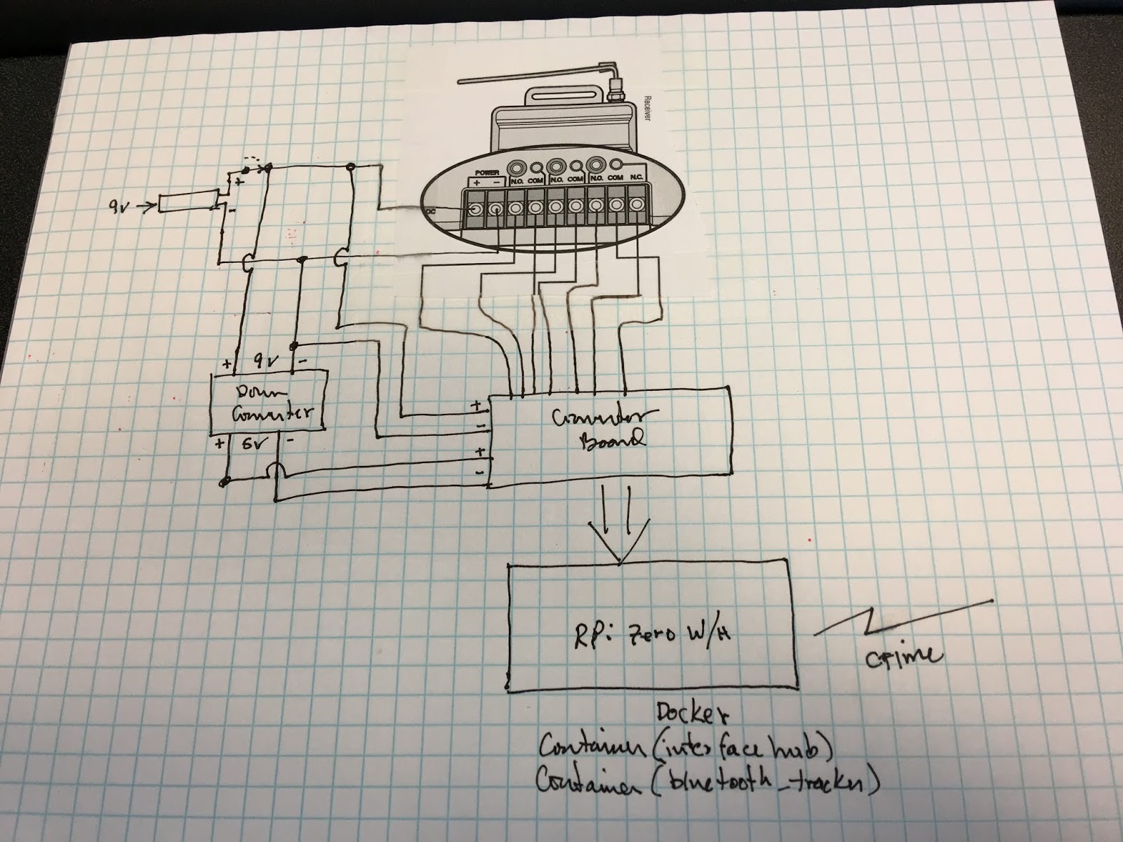
The converter board will actually be a breadboard connected to the RPiZW gpio pins. I am planning to initially mount the Down Converter (Buck) to the same breadboard. However, I need to get everything set up first before moving the parts to the RPiZW breadboard. So, the initial physical setup looks like this:

The RPiZW is rather small compared to the LiftMaster 850LM, so piggy backing everything on one breadboard for the prototype is probably ok. I also need to figure out a model to print from my 3D printer to contain everything.
Tuesday, August 14, 2018
HomeLink HA Interface #2 - Experiments with the LiftMaster 850LM
So I decided to go ahead and test out the LiftMaster 850LM to see what I was up against. This device will become central to how I am going to interface my home automation system to my car. I have always been a little upset that there were no interface devices to link my car to other than a simple switch or a garage door. That is shallow thinking on the part of the automotive industry and the people who make garage door devices. Anyway I digress.
The 850LM is going to be used to detect button clicks from my car and convert those clicks to MQTT messages that will be sent to my home-assistant controller via an MQTT broker. I expect to interface this on a Raspberry Pi Zero W (RPi0W) using its gpio pins. However, there are a couple of issues that need to be resolved. The gpio pins on the RPi take 3.3v and the lowest voltage DC that the 850LM can handle is 9v. Fortunately, I noticed previously that the Adafruit bi-directional level shifter can take a high side voltage up to 10vDC. That means that I can use the level shifter between the 850LM and the RPi0W. The main reason that I want to use the RPi0W for this interface is that I can run the software under a Docker container, and allow for another container to House a Bluetooth proximity sensor / MQTT setup. Note that the RPi0W needs a 5v DC power source, but generates its own 3.3v power for the gpio.
The 850LM has a power port as well as a screw connection marked plus and minus. It has a total of three relay connections; the first two having NO / GND screw terminals and the third having NO / GND / NC screw terminals. So my first question was how do the power port and power screw terminals relate. The second question was when the relays switch is it momentary (governed by how long you press the button on the car), is it momentary (fixed close then open time), or is it more of an on / off switch (changes as you click the car button). Fortunately, I should be able to use a remote control to do the testing.
Test 1: I powered up the 850LM using a 5v to 9v usb cable that I had lying around by plugging it into the power port. I had to use an adapter because the center pin on the power port was thick (white size). Once powered up, I had no problem setting up the remote control by following the 850LM instructions (click yellow button on 850LM, led next to button flashes, click button on remote, led goes out). Once I did this, a click on the remote caused the relay to close and then open on its own. So I answered the second question. It makes sense because most garage door controllers have wall switches that momentarily close a connection which starts the garage door motor running.
Test 2: I then checked the power terminal pins and discovered that there was on voltage in the millivolt range. This means that I cannot power the 850LM and draw power from these terminals when the 9v supply is plugged into the power connection.
Test 3: while clicking on the remote, I checked the voltage levels appearing between the NO / GND terminals. This did not measure any change from zero volts. This means that I will need to use a pull-up resistor for transitioning on the level shifter. It also means that I will need to deal with negative logic; high showing up on the gpio means False / 0 / not clicked, and low means True / 1 / clicked. I might end up using interrupts instead of running everything through a loop in order to not interfere with other container programs.
Test 4: I connected my 9v power source to the power screw terminals. I checked the on / off with my remote and everything worked out just fine. So I will be connecting the 9v source (via a barrel to screw terminal adapter) to these terminals, along with the input side of a Buck converter (to give 5v from the 9v source) and some connection wires to power up the high side of the level shifter. What I may do instead is put everything on a breadboard connected to the RPi0W gpio and minimize the connections needed (use the breadboard as the connection points for all of it).
I wonder if I can mount the Buck converter on the breadboard as well, that would save some space for me. I am also concerned that the Buck converter might interfere with the functioning of the RPi, but I will have to test that out as everything is built.
I wonder if I can mount the Buck converter on the breadboard as well, that would save some space for me. I am also concerned that the Buck converter might interfere with the functioning of the RPi, but I will have to test that out as everything is built.
Thursday, July 12, 2018
HomeLink HA Interface #1 - Development of a RPi Based Integration with a Liftmaster 850LM and Home Assistant
Not long ago I became interested in Home Automation. This occurred as a result of making plans to add some more living space to my house. I figured if I was going to spend some money on my house I should add some new capabilities as well. I found out about Home-Assistant and was intrigued by the idea of being able to integrate disparate manufacturer's devices into the same mix along with being able to control them from the same source. The problem with going to any one vendor is that they want you in their ecosystem; hence when you have many devices you end up with say many apps on your phone. I wanted to do everything with one, or do it by voice, but be able to pick and choose what device I want where. The war between Insteon and Z-Wave be damned.
So here is the brain-fart. I have a Subaru Forester that has a set of HomeLink buttons on the auto-dimming rear-view mirror. I don't have a garage, but I do have a porch with lights. So, my first interaction was to add a Chamberlain light switch to the porch lights which I can command to go on and off from one of the HomeLink buttons. Now I can turn on the porch lights when I get home late, and turn them off when I get in the house. That was very little effort and I did that before I decided to go into Home Automation. I removed a dimmer switch to put in the Chamberlain light switch. I miss the ability to dim the lights on the front porch. Why can't I have both a dimming capability and a HomeLink turn on and off ability. In fact, why can't I use the HomeLink buttons to key off a "scene" like turn on the porch lights (if it's dark outside), turn off the living room lights, lock the door, set the alarm, wait for x minutes so you can get out of the driveway before turning off the porch lights? Then, when I come home I just use a different HomeLink button to do the reverse? Hence my desire to integrate something into the Home Automation sequence using HomeLink.
I was able to locate / buy a Liftmaster 850LM switch which has the ability to integrate with the HomeLink switches and garage door opener remote controls. Normally it is used to control a garage door, but interestingly enough, I can sense the latches with an ESP8266 / Arduino / Raspberry Pi (take your pick) and push out the state of those latches using MQTT to the Home Assistant automation platform. If I want, I discovered that the 850LM can run on as little as 9 volt DC input. The Adafruit 757 bi-directional logic level converter has a max input on the high side of 10 volts which means that I could go through the 757 from the 850LM to whatever device I want to sense the state change. I can then use the chosen device to use MQTT to send state information changes to the Home-Assistant center. If I am real smart I can use a length of time timer that a HomeLink button is held down to increase the number of different states that I can report and if I use an RPi with Docker I can do other things at the same time. Oh, and two clicks within 1 second would give me a third level, but let’s not get ahead of ourselves. Anyway, it's worth investigating.
So now to get from Brain-Fart to working system.
So here is the brain-fart. I have a Subaru Forester that has a set of HomeLink buttons on the auto-dimming rear-view mirror. I don't have a garage, but I do have a porch with lights. So, my first interaction was to add a Chamberlain light switch to the porch lights which I can command to go on and off from one of the HomeLink buttons. Now I can turn on the porch lights when I get home late, and turn them off when I get in the house. That was very little effort and I did that before I decided to go into Home Automation. I removed a dimmer switch to put in the Chamberlain light switch. I miss the ability to dim the lights on the front porch. Why can't I have both a dimming capability and a HomeLink turn on and off ability. In fact, why can't I use the HomeLink buttons to key off a "scene" like turn on the porch lights (if it's dark outside), turn off the living room lights, lock the door, set the alarm, wait for x minutes so you can get out of the driveway before turning off the porch lights? Then, when I come home I just use a different HomeLink button to do the reverse? Hence my desire to integrate something into the Home Automation sequence using HomeLink.
I was able to locate / buy a Liftmaster 850LM switch which has the ability to integrate with the HomeLink switches and garage door opener remote controls. Normally it is used to control a garage door, but interestingly enough, I can sense the latches with an ESP8266 / Arduino / Raspberry Pi (take your pick) and push out the state of those latches using MQTT to the Home Assistant automation platform. If I want, I discovered that the 850LM can run on as little as 9 volt DC input. The Adafruit 757 bi-directional logic level converter has a max input on the high side of 10 volts which means that I could go through the 757 from the 850LM to whatever device I want to sense the state change. I can then use the chosen device to use MQTT to send state information changes to the Home-Assistant center. If I am real smart I can use a length of time timer that a HomeLink button is held down to increase the number of different states that I can report and if I use an RPi with Docker I can do other things at the same time. Oh, and two clicks within 1 second would give me a third level, but let’s not get ahead of ourselves. Anyway, it's worth investigating.
So now to get from Brain-Fart to working system.
Thursday, June 14, 2018
I've gone overboard with the SD Cards
I was sitting at my kitchen table last night getting all of my RPi SD cards organized. I just realized that I have gone overboard - I now have a total of 70 plus cards that do various things and are in various levels of completion. Do you think I have a case of hoarder fever? Must needs to reuse cards that I haven't touched in a while. I know it is that many cards since I have all of them numbered. Good grief!!
Monday, March 26, 2018
Docker Test #1 - setting up test platform
So I decided to go out and get a couple of parts to start running some Docker tests. I was able to get a Raspberry Pi Zero WH from my local MicroCenter. To that I added a USB-A connector (https://www.amazon.com/gp/product/B077W69CD1) and an OLED display (https://www.amazon.com/gp/product/B078D6NXFM) so that it is all one compact unit as shown here:


I wanted to be able to use the WiFi and Bluetooth capabilities as well as have a small OLED display with some control switches that I could use to control different Docker Containers as I develop them. There are a few hoops that I need to get through to accomplish this.
I wanted to be able to use the WiFi and Bluetooth capabilities as well as have a small OLED display with some control switches that I could use to control different Docker Containers as I develop them. There are a few hoops that I need to get through to accomplish this.
- Install Redmine, get it configured for general projects
- Install Docker repository, integrate with Redmine (MySQL? Git repository?)
- Start Redmine project for test
- Get test install working on RPi for OLED screen, including buttons
- Install Docker on RPi
- Pull test into container, record steps,
- Run test to ensure it works correctly
- Push test container to local repository
- Split test code into two pieces, one for OLED explicitly and one for test code
- Pull two piece test code into two containers
- Run combined test to ensure it works correctly
- Push combined test containers to local repository
I am not going to do each of these in a specific order, however I will document what I do in this post and in
posts to follow. The first thing that I wanted to get accomplished was the setup of the Raspberry Pi.
- first, I mechanically put the docker test platform together
- next, I setup a 16GB micro SD using my Mac Mini with the following commands:
df -k
sudo diskutil unmount /dev/disk3s1
sudo dd bs=1m if=2015-02-16-raspbian-wheezy.img of=/dev/rdisk3
note that I actually used a newer version of raspbian (Stretch) since I was planning on keeping
this as up to date as I possibly could.
- next, I changed two files on the /boot directory of the micro SD.
cd /Volumes/boot
nano wpa_supplicant.conf
ctrl_interface=DIR=/var/run/wpa_supplicant GROUP=netdev
network={
ssid="YOUR_NETWORK_NAME"
psk="YOUR_PASSWORD"
key_mgmt=WPA-PSK
}
touch ssh
- next, I unmounted the micro SD and checked to see that it was unmounted
sudo diskutil unmount /dev/disk3s1
df -k
- next, I installed the micro SD, booted the RPi, checked my router for the IP address of the RPi,
and set ssh on, SPI on, time zone, and expand microSD using raspi-config
- I rebooted the RPi and performed and update
sudo apt-get update
sudo apt-get upgrade
- next, I went to the website for the WaveShare OLED display at
https://www.waveshare.com/wiki/1.3inch_OLED_HAT, gathered some reading material, and started
loading libraries from the instructions at https://www.waveshare.com/wiki/Libraries_Installation_for_RPi.
- I did manage to bork the install of the docker suite using:
curl -sSL https://get.docker.com | sh
I'm not sure of what happened but it appears that the setup I am using has some issues with
power. I apparently need more than some usb cables that I own of being able to provide enough
power; the most success that I have had was using a powered usb hub from Smays which also
doubles as an ethernet connector. Now it appears that I will have to go back and remove docker
and re-install it on my system.
curl -sSL https://get.docker.com | sh
I'm not sure of what happened but it appears that the setup I am using has some issues with
power. I apparently need more than some usb cables that I own of being able to provide enough
power; the most success that I have had was using a powered usb hub from Smays which also
doubles as an ethernet connector. Now it appears that I will have to go back and remove docker
and re-install it on my system.
Saturday, January 6, 2018
LED - Light Controller #3 - I always seem to never have enough time to complete projects
As usual, I am here after a long period of time without completion of my project. During my time away from my little projects, it occurred to me that I might have a problem with the way that I was doing this project. I had a workable solution, bread-boarded part of it and connected the raspberry pi to it, putting a simple python program onto it and exercising the 8-channel relay. After checking things out, I started putting the elements together and soldering them to a perma-proto board from Adafruit. Sure enough, when I started soldering the 24 pin chips onto a breadboard I ended up smoking them. I found myself completely unable to switch the 8-channel relay at this point.
At this point I started rethinking my approach to development. Even though I had plenty of Raspberry Pis to go around, I started thinking about other solutions. In my network, I have a vlan specific to Experimenting. I also have a bunch of switches that allow me to setup links all over the house. It occurred to me that maybe I could use an ESP8266 NodeMCU chip to receive commands and cause the switching to occur. That way, I could use a Raspberry Pi to do the commands. I could also simply print each of the boxes and tailor them to my circuitry. So that is where I am at.
At this point I started rethinking my approach to development. Even though I had plenty of Raspberry Pis to go around, I started thinking about other solutions. In my network, I have a vlan specific to Experimenting. I also have a bunch of switches that allow me to setup links all over the house. It occurred to me that maybe I could use an ESP8266 NodeMCU chip to receive commands and cause the switching to occur. That way, I could use a Raspberry Pi to do the commands. I could also simply print each of the boxes and tailor them to my circuitry. So that is where I am at.
Friday, December 22, 2017
LED - Light Controller #2 - Hardware Buildout for Light Controller Box
The idea for a Light Controller Box is from the old idea of an internet controlled switch. You have some type of control that sets or unsets a relay so that power is turned on/off at a plug. Normally these things are in racks of equipment and are used for emergency shutdown and reducing power in a network room when a server is not needed. The idea suits my needs because I want to be able to switch a string of lights on and off. This is the basis for many of the light shows that you can find videos from on YouTube.
First off, I wanted something to keep the equipment dry and at the same time be able to run the power cables as necessary. At first, I thought about using a cheap toolbox and cutting out holes for the power ports and switches. One other thing that I was going to have to do was to figure out some sort of seal around the lid and some way to waterproof the connections going into the toolbox. However, after thinking about it, I decided that this was too much work on my part for what I was getting. I wanted something that I could buy and quickly setup as necessary since I was going to need a couple of these. So I settled on the idea of a DriBox which is a plastic box that has openings for power cables so that you can put say a power strip in it and plug cables into it. The cables are put into slots in the box that have grommets that fit around the power cables when the lid is put back on. It is not completely waterproof, but you can run a hose on it and it does keep the contents dry.

Next, I figured that I could take the electronics and put them on a piece of Plexiglas with standoffs that could be screwed into the Plexiglas along with some "feet" on the other side. That way, I could put everything together, check it out and then put it into the box quickly. That would save a lot of time for repairs. I could also re-purpose the electronics to another project later by simply removing the Plexiglas board from the DriBox and unscrewing the power lines. I also chose to put the 16 port io extenders on a full size Adafruit perma-proto board with connectors pointing up so that this could be reused as well. Prototyping of the whole circuit can be done on a regular breadboard and then moved over to the perma-proto board because the connections are identical. There is even space on the board for the connector to the Raspberry Pi.

The next post will have a circuit diagram for the 16 port extension. I might even invest in a RPi hat that has the same characteristics if I can find one.
First off, I wanted something to keep the equipment dry and at the same time be able to run the power cables as necessary. At first, I thought about using a cheap toolbox and cutting out holes for the power ports and switches. One other thing that I was going to have to do was to figure out some sort of seal around the lid and some way to waterproof the connections going into the toolbox. However, after thinking about it, I decided that this was too much work on my part for what I was getting. I wanted something that I could buy and quickly setup as necessary since I was going to need a couple of these. So I settled on the idea of a DriBox which is a plastic box that has openings for power cables so that you can put say a power strip in it and plug cables into it. The cables are put into slots in the box that have grommets that fit around the power cables when the lid is put back on. It is not completely waterproof, but you can run a hose on it and it does keep the contents dry.

Next, I figured that I could take the electronics and put them on a piece of Plexiglas with standoffs that could be screwed into the Plexiglas along with some "feet" on the other side. That way, I could put everything together, check it out and then put it into the box quickly. That would save a lot of time for repairs. I could also re-purpose the electronics to another project later by simply removing the Plexiglas board from the DriBox and unscrewing the power lines. I also chose to put the 16 port io extenders on a full size Adafruit perma-proto board with connectors pointing up so that this could be reused as well. Prototyping of the whole circuit can be done on a regular breadboard and then moved over to the perma-proto board because the connections are identical. There is even space on the board for the connector to the Raspberry Pi.

The next post will have a circuit diagram for the 16 port extension. I might even invest in a RPi hat that has the same characteristics if I can find one.
Thursday, December 21, 2017
LED - Light Controller #1 - Introduction and Idea
I have been thinking about next Christmas season and I have decided to get my act together and put together a LED Strip Controller Helix and Light Switching Box. I want it to be RPi/Arduino controlled and interfaced to my home network.
The requirements for Light Switching Box are as follows:
The requirements for the LED Strip Controller Helix are as follows:
The requirements for Light Switching Box are as follows:
- Circuit A and B, with inputs A and B from mains
- 8 individually switched circuits - one socket per
- Main switch toggles off, circuit A or circuit A+B - real switch
- Fuses on incoming?
- One socket always connected to circuit A for RPi, always powered when A is plugged in
- Connection to RPi through I2C, 16 port ic through level shift
- 8 ports used for 8-port relay, remaining 8 ports for switch and led functions?
- RGB led for boot up/armed function, RGB led for other indication
- Triple LED strip controller PCM (WS2812B)
- Base the light on a helical strip wrapped around a 4 inch pvc pipe. I can get about 4.5 inches in between each coil on a four foot section and make use of the controls in each
- Cap the top so that water cant get in
- Place an Arduino and power supply, for the LED strip, inside the pipe to keep it out of the weather. If the Arduino can be controlled wirelessly, I can communicate with it to send update commands with my home network.
- Four wire line (for power and i2c data/clock) in the case of a non wirelessly controlled Arduino or, a Two wire line (for power) in the case of a wirelessly controlled Arduino controller. Power only going into the box is obviously preferred.
- Communicate from the Light Switching Box to each Helix to relay commands and synchronize the light show.
Saturday, December 31, 2016
holding off for a bit!
I have decided that I need to take a break from updating this blog. Will be back in the near future.
Thursday, December 29, 2016
IPSec VLAN #2 - Hardening Rules
After review of information in this SANS 2006 document, I am a little more confident that I can implement the Gateway into my house with a more controlled hardening. This document is a design using open source components for an Intrusion Detection/Prevention System. It applies to a small to medium network which is appropriate for my home environment. My thought is to have this implemented prior to the OpenVPN server in the IPSec VLAN setup that I am building. Additionally, I will be using SELinux to lock down the services running on my OpenVPN RPi server. So at this point the following would be needed:
- IDS/IPS in the flow between the internet connection and the OpenVPN server.
- SELinux used to lock down services in the RPi server.
- Checks to make sure that the OpenVPN stream is not broken/compromised, if so then stop all traffic incoming to the home network (meaning the IPSec streams would stop).
- Audit logs of activity and regular checking of the logs to ensure that nothing got by.
- No DHCP service on No Man's Land LAN.
- No ICMP ping responses from any device connected to No Man's Land LAN, this might include any detection of scanning in the network and/or detection of pen test tools.
IPSec VLAN #1 - Keeping VLANs Separate Using Encryption
I was reviewing some Capability Package (CP) documents from NSA the other day and it occurred to me that one of the ideas I could use was to keep VLANs separate from each other even across the internet. This has appeal since I have a couple of VLANs in my home network that are not connected to the outside world or each other, yet I want to be able to do something with them during lunch at work.
Without going into too much detail re: the CP from NSA, they describe a virtual private network using commercial products which keep security domains separate from each other. This is done through a double encryption linkage. The following illustrates what I am talking about:

In this diagram, an OpenVPN Gateway is used on both sides (with certificate based connection) to form a connection between two No Man's Land LANs. This is roughly equivalent to what we normally do on a day to day basis connecting a laptop using an OpenVPN client to our home networks through an OpenVPN server. That being said, the connection goes between two LANs that do nothing in this diagram except give a place to combine packets from multiple IPSec VPN Gateways. If we use a separate certificate to access each "VLAN", the information will not cross between them. In other words, I could have an IPSec VPN Gateway at work, with a certificate for LAN A, and I could only connect through IPSec VPN Gateways at home that used the same certificate. Those would be ones that are part of the same LAN A "VLAN". Notice that I don't have to have a switch/router that is VLAN aware; I could have everything on separate conventional networks.
My thought is to implement OpenVPN on a RPi which would serve as an OpenVPN Gateway into the No Man's Land LAN (after hardening the RPi to attack of course, using a certificate specific to the OpenVPN connection). I would then implement IPSec VPN Gateways on other RPis (also hardened to attack) with certificates specific to the LAN that they connect to. This speaks of having my own certificate authority (which is food for another post). The OpenVPN Gateway doesn't necessarily need to be on an RPi either; I just would like to see if I can get this working using commodity items. Note that the IPSec VPN Gateways could be implemented in VMs as well running on a server.
More Later.
Without going into too much detail re: the CP from NSA, they describe a virtual private network using commercial products which keep security domains separate from each other. This is done through a double encryption linkage. The following illustrates what I am talking about:

In this diagram, an OpenVPN Gateway is used on both sides (with certificate based connection) to form a connection between two No Man's Land LANs. This is roughly equivalent to what we normally do on a day to day basis connecting a laptop using an OpenVPN client to our home networks through an OpenVPN server. That being said, the connection goes between two LANs that do nothing in this diagram except give a place to combine packets from multiple IPSec VPN Gateways. If we use a separate certificate to access each "VLAN", the information will not cross between them. In other words, I could have an IPSec VPN Gateway at work, with a certificate for LAN A, and I could only connect through IPSec VPN Gateways at home that used the same certificate. Those would be ones that are part of the same LAN A "VLAN". Notice that I don't have to have a switch/router that is VLAN aware; I could have everything on separate conventional networks.
My thought is to implement OpenVPN on a RPi which would serve as an OpenVPN Gateway into the No Man's Land LAN (after hardening the RPi to attack of course, using a certificate specific to the OpenVPN connection). I would then implement IPSec VPN Gateways on other RPis (also hardened to attack) with certificates specific to the LAN that they connect to. This speaks of having my own certificate authority (which is food for another post). The OpenVPN Gateway doesn't necessarily need to be on an RPi either; I just would like to see if I can get this working using commodity items. Note that the IPSec VPN Gateways could be implemented in VMs as well running on a server.
More Later.
Wednesday, September 14, 2016
Cluster #4 - Implementing the IPSec VPN as Client and Server
I am working on a solution for security in my house based on an IPSec tunnel. This is partially based on a NSA capability package document re using commercial off-the-shelf encryption techniques for separation of security domains. The idea was interesting enough to try and replicate as part of my home VPN interconnections.
I have been reviewing a number of different posts to get this working, see here, here, and here. Internet Protocol Security (IPsec) is a protocol suite for secure Internet Protocol (IP) communications by authenticating and encrypting each IP packet of a communication session. The major contender package is StrongSwan rather than OpenVPN which does not support IPSec.
I have been reviewing a number of different posts to get this working, see here, here, and here. Internet Protocol Security (IPsec) is a protocol suite for secure Internet Protocol (IP) communications by authenticating and encrypting each IP packet of a communication session. The major contender package is StrongSwan rather than OpenVPN which does not support IPSec.
Saturday, September 3, 2016
Setting up DHCP, NTP, DNS, Radius, and LDAP on a Raspberry Pi
I have been a little bit busy lately and have not had a chance to get back to the RPi things that this blog is all about. Part of that time was learning some things on my new 3D Printer, but that is for another blog post because it will come to play in the future.
I decided that I wanted to setup a simplified server for use on a given vlan and/or a use-case in which I need these services and do not want to rely on a router. So I will need the following services:
Seems like a tall order but it is just setting up things in an orderly manner.
I decided that I wanted to setup a simplified server for use on a given vlan and/or a use-case in which I need these services and do not want to rely on a router. So I will need the following services:
- DHCP - gives out IP addresses for the subnet that it is connected to
- NTP - provides a time service for the subnet
- DNS - provides a localized domain name service for the subnet
- Radius - provides Authentication and Authorization for the subnet, specifically for switches and wireless access points
- LDAP - provides directory services for the Radius server to maintain username/password combinations, allowed MAC addresses, ranges for subnet addresses
- Webmin - provides a web based server update process
Seems like a tall order but it is just setting up things in an orderly manner.
Thursday, July 14, 2016
Bringing Back the 1-Port Router
Ok, now I need to set up a Raspberry Pi 1-Port Router. I know how to accomplish this (see the article here), I just have to go through the motions to implement it. Strange - I am on SD052; I'm going to have to quit buying these things and start reusing the ones that I already have. The setup was as follows:
sudo apt-get update
sudo apt-get upgrade
sudo apt-get install vlan shorewall
Then to get webmin setup and running, I did the following:
I added to /etc/apt/sources.list -
deb http://download.webmin.com/download/repository sarge contrib
I then got the key for the webmin repository -
sudo wget http://www.webmin.com/jcameron-key.asc
sudo apt-key add jcameron-key.asc
I then installed webmin -
sudo apt-get install perl libnet-ssleay-perl openssl libauthen-pam-perl libpam-runtime libio-pty-perl apt-show-versions python
sudo apt-get install webmin
I am going to use the 1-Port Router to connect between three different vlans, vlan4, vlan6, and vlan8. Webmin will be used to setup the routing functions on Shorewall so that I can do the following:
I am going to accomplish this by the following setup (TBD).
sudo apt-get update
sudo apt-get upgrade
sudo apt-get install vlan shorewall
Then to get webmin setup and running, I did the following:
I added to /etc/apt/sources.list -
deb http://download.webmin.com/download/repository sarge contrib
I then got the key for the webmin repository -
sudo wget http://www.webmin.com/jcameron-key.asc
sudo apt-key add jcameron-key.asc
I then installed webmin -
sudo apt-get install perl libnet-ssleay-perl openssl libauthen-pam-perl libpam-runtime libio-pty-perl apt-show-versions python
sudo apt-get install webmin
I am going to use the 1-Port Router to connect between three different vlans, vlan4, vlan6, and vlan8. Webmin will be used to setup the routing functions on Shorewall so that I can do the following:
- Have a firewall facing out towards vlan4 from vlan6; supply dhcp services to vlan4; allow only traffic from the Mac Mini to vlan4 from vlan6; and provide a one-to-one NAT ip from my WD MyCloud onto vlan4.
- Have a firewall facing out towards vlan8 from vlan6; supply dhcp services to vlan8; allow only traffic from the Mac Mini to vlan8 from vlan6; and provide a one-to-one NAP ip from my ubuntuServer VM cluster.
I am going to accomplish this by the following setup (TBD).
Sunday, July 3, 2016
Cluster #3 - Rearranged the Cluster for Experimentation
One of the issues that I have fixed is how to take each one of the RPis in the Cluster and be able to independently move them from one location to another. I was able to achieve this by the use of a Netgear 116E 16-port managed switch. Since I have 4 RPis in the cluster, I took up 8 ports on the switch and managed to be able to move things around at my convenience. This was evident when I decided to take .101 and tie it to the same vlan as .100. However, in this case I started up an openVPN setup following the instructions at https://github.com/StarshipEngineer/OpenVPN-Setup. By having .101 on the switch, I was able to easily move the head from the LAN1 vlan to the CEH input vlan. Now I can setup the openVPN independently from what I was intending on doing with .100.
Another interesting tidbit was that I was able to hook up the PowerLine adapter to the No-MansLand vlan in another area in my house and connect to it via the other PowerLine adapter on my front porch. So I was able to do some updates to the RPi while sitting on my porch - and No-MansLand vlan was separated from the outside world. Now what I want to be able to do is access specific vlans from outside using a double IPSec encryption setup. More later.
Another interesting tidbit was that I was able to hook up the PowerLine adapter to the No-MansLand vlan in another area in my house and connect to it via the other PowerLine adapter on my front porch. So I was able to do some updates to the RPi while sitting on my porch - and No-MansLand vlan was separated from the outside world. Now what I want to be able to do is access specific vlans from outside using a double IPSec encryption setup. More later.
Saturday, June 11, 2016
Weather Station Project #27 - Took some samples through material
This morning I was out in the yard setting up an experiment. I connected the Solar Radiation/UV Sensor setup to a POE enabled cable connected to a Ethernet over Power Line adapter. The other Power Line adapter I plugged into my computer downstairs in the computer room. This adapter was plugged into a Pers VLAN connector on one of my GS108Ts. By doing this, I was able to connect to the sensor setup using my laptop on the porch through wi-fi. I am going to leave the connection downstairs so that I will be able to use the Power Line adapter in other VLANS as necessary. It was neat to get it working. Here is a picture of the parts on my porch table.

This UV data shows a loss of about 5 and a half percent in the visible spectrum, 4 and a half percent considering the IR spectrum. The overall percent difference between my local site and the site that I am using for calibration appears to be about 2.8 percent; my value is higher. The distance between us is about 4.13 miles so I have been assuming that the values should be about the same.
According to this data, I should not have a problem if I used the lid to my sandwich container (plastic cover in the test). I just have to compensate for the loss; there doesn't appear to be a loss associated with the UV sensitivity as far as I can tell. So I should multiply my UV readings by 1.0628 to get the same as the Kingstowne values? I should multiply my uvVIS values by 0.4979 to get the watts/m^2 equivalent to the values from the site where I am comparing my values.
The values of the data that I took was as follows:
results with no cover in bright sunlight
{ "tslLUX":"65536.00", "uvVIS":"1677.00", "uvIR":"13354.00", "uvUVRaw":"761.00", "uvUV":"7.61" }
reading from site was 12.0 for UV
Kingstowne says 7.4 UV, 835 watts/m^2
results with plastic cover in bright sunlight
{ "tslLUX":"65536.00", "uvVIS":"1594.00", "uvIR":"12876.00", "uvUVRaw":"716.00", "uvUV":"7.16" }
results with polycarbonate in bright sunlight
{ "tslLUX":"65536.00", "uvVIS":"1600.00", "uvIR":"13228.00", "uvUVRaw":"720.00", "uvUV":"7.20" }
Kingstowne says 6.9 UV, 796 watts/m^2
results with soda glass in bright sunlight
{ "tslLUX":"65536.00", "uvVIS":"1627.00", "uvIR":"12333.00", "uvUVRaw":"734.00", "uvUV":"7.34" }
Kingstowne says 7.2 UV, 833 watts/m^2
results in the shade with no cover
{ "tslLUX":"2152.00", "uvVIS":"312.00", "uvIR":"962.00", "uvUVRaw":"30.00", "uvUV":"0.30" }
{ "tslLUX":"2168.00", "uvVIS":"315.00", "uvIR":"976.00", "uvUVRaw":"31.00", "uvUV":"0.31" }
Kingstowne says 6.7 UV, 817 watts/m^2
According to this data, I should not have a problem if I used the lid to my sandwich container (plastic cover in the test). I just have to compensate for the loss; there doesn't appear to be a loss associated with the UV sensitivity as far as I can tell. So I should multiply my UV readings by 1.0628 to get the same as the Kingstowne values? I should multiply my uvVIS values by 0.4979 to get the watts/m^2 equivalent to the values from the site where I am comparing my values.
Subscribe to:
Posts (Atom)