Labels

Wednesday, December 4, 2013

I now have a personal cloud device in the home network

I just purchased a Western Digital My Cloud drive (3TB) and added it to my network in the Pers vlan.  Right up front I can say that I am very pleased with this drive and how it operates.  The My Cloud drive has a 1GB Ethernet port and a USB 3.0 port on the back.  The 1GB Ethernet gives the drive plenty of flexibility to stream media content within the house, so I am planning on using it to host both video and audio files for use throughout.  I have also connected a 4TB backup drive to the USB 3.0 port on the back, giving a total of 7TB of storage.

I was able to get the drive up and running through the WD website for use with my iOS apps.  The 4TB drive shows up as a share on the drive, which is perfect.  Unfortunately, my work network's proxy server doesn't recognize the WD website, so I had to go through our guest wireless to test out general access via PC from work.  I was able to log into the WD website and select one of the shares to be opened in Windows Explorer, and it came right up.  So that is an interesting way to interface to the drive from the outside.  It appears that Western Digital did their homework.

The problem that I am currently facing is that the My Cloud drive is on my Pers vlan while the media components (that would make use of the video and audio file storage) are on the Media vlan.  At the moment I am in the process of setting up an Ubuntu VM to be the router between the Pers and Media vlans.  My constraints are as follows:

  • Use Shorewall firewall on Ubuntu VM to do routing; propose using Media and Pers zones; connection is via the vlans that were created on the Thunderbolt interface.  These show up as different ethX devices in the Ubuntu VM
  • Using 1 to 1 NAT, present the Mac Mini and the My Cloud drive on the Media vlan with Media vlan IPs
  • Setup firewall to allow connection to iTunes protocol, AFS protocol, SMB protocol, and http protocol on the My Cloud drive from Media vlan
  • Setup firewall to allow connection to iTunes protocol, AFS protocol on the Mac Mini from Media vlan
More later.

Tuesday, November 26, 2013

Some Thoughts on a Remote Wireless Access Device

The thought occurred to me today that I might want to set up a version of the RPi Router that would be able to be an extension of my home system.  What I want to do is take the RPi Router into my office at work, turn it on, and have it use the same SSID, but via an SSH tunnel, go into my system at home.  I would need to be able to:

  1. Use dual wi-fi access, provide a connection to the work wi-fi network (with auto authentication) and provide the same SSID as my home.  Not sure if I need two USB wi-fi dongles or not.
  2. The connection should use an SSH tunnel which is kept up in the background, allowing me to use any of the systems that I have in my house.
  3. Somehow, this RPi Router should provide a DHCP forwarding from my house to whatever device hooks into the router.  I may be able to use my new FVS318N router to accomplish some of this, since it does provide VPN capabilities (in case I cannot get the SSH tunnel to do it).  An RPi based VPN for using the FVS318N anyone?
  4. Should be plug and play, i.e. put in the SD card and plug in the RPi to get it to function.  Wishing for the moon at the same time.
This obviously is a variation on some of the 1-Port Router ideas that I have had in the past.

Monday, November 18, 2013

Got in the new RFDuino

I received my incentive from the RFDuino kick starter program. I sincerely hope that the individual who started this is successful. This is a quality piece of work. I can't wait to try it out.


Thursday, November 7, 2013

Issue with the FVS318N Router

I am slowly learning how to incorporate the FVS318N.  However, now I discover that there is apparently no way to setup VLAN to VLAN rules.  The router gives you the ability to make some rules for LAN to WAN, LAN to DMZ, and DMZ to WAN, but no LAN to LAN (or in my case VLAN to VLAN).  I did discover that there is a CLI (command line interface document that details some newer aspects of the router, but a cursory look into the command set did not give me the impression that there was a way to setup LAN to LAN rules.

My main motivation in setting up the LAN to LAN rules is to allow the Media VLAN to be able to access the Plex server running on my Mac Mini which is on a completely separate VLAN.  In addition to that, I use the Mac Mini as the main workstation for modifying the routers and switches in my home network.  Yea, I know, way too much - but I enjoy doing what I do.  I was thinking that I might try my hand at setting up either a Raspberry Pi router or setup a VM on the Mac Mini to do the routing.  What would be perfect is if I could do it on the new FVS318N.  This router will be able to replace about 3 devices if I succeed. 

Update: I figured out that if I use a "1 to 1 NAT" from a router, I can have an IP show up in one VLAN from a device resident in another VLAN with a different IP.  I am currently working the issue using a VM on the Mac Mini to do the routing with Shorewall.  Once I get that up and running, I will transfer it to a Raspberry Pi router which will be on all the time.

Monday, November 4, 2013

Found an interesting thing while using one of my routers

This weekend while fooling around with one of my routers, I chanced to put the WAN input of the main router onto my DMZ vlan.  I was able to have a full connection to the outside after I got rid of the first ethernet cable that I was using (it did not register as being connected).  When I connected the main router to my DMZ vlan, I noticed that I had a GHz connection (thanks to the GBit switch that I was using) and I was able to connect to the outside with no apparent slowdown of the speed.

I still have an issue though, because I set up the ActionTec router to route specific ports to my main router.  However, with this new connection, I have a means of controlling pretty much everything in the house.  I was wondering how I might fit my new FVS318N router into the mix.  Originally, I was going to put it upstairs and replace 3 devices (my main router, the upstairs switch and the router I use with the media vlan downstairs).  The media vlan router is connected into the DMZ vlan in the downstairs bedroom.  I was going to use the FVS318N to replace it as I could set up multiple dhcp servers, each tuned to a separate vlan.  This has been the issue throughout my house as I expand the capabilities of my setup.

Sounds like I need to explore a little more of what vlans can do for me.

Saturday, September 21, 2013

Portable Pi Project - Part #1

Well I now have some challenges ahead of me. I have decided that I need to make a portable RPi layout for testing. The idea is to bring it in to work to have around during lunchtime, when I get a chance to eat a bowl of soup. I figure if I put an RPi, hub, battery, various USB devices, external wifi adapters, the RPi camera, etc. on a sheet of Lexan I can make good use of it. This will allow me to code and test out some projects while being able to put the RPi into my bag in the morning.
I think that putting the equipment between two sheets of Lexan, with enough standoffs, I should be far enough along. The real problem is the orientation of the peripheral ports. I need to get to the USB, Ethernet, HDMI, SD card slot and maybe the GPIO from the side of the setup. The SD card slot is needed to change out different experiment setups. The others are self explanatory.
If I get it tied down enough with a sufficiently narrow width, it should work.
Update:  I purchased two 8x10 sheets of Lexan from my local Home Depot, along with 6 - 1" plastic standoffs, 4 rubber feet, and mounting hardware.  I wasn't able to find M3 screws or nuts but I did have some that I purchased at a different time.  It turns out that 6-32 will not fit into the mounting holes of the RPi, but M3 will.  I was able to take 1/2" standoffs and cut them in half with a PVC pipe cutter (does a really good job BTW). I mounted the RPi in one corner with the power and SD card slot about 1/4" from the edge; this has the SD card sticking out when it is mounted, but makes it easy to change out.  I wanted to be able to get to the SD card slot for changing the peripheral.  Now my issue is mounting of the other elements.  I figure that I should take apart the USB hub and that should make it easier to mount in the shell.  The current state of the configuration is shown in the following picture.


I am planning on mounting the USB Hub in the center of the left side in the photo (the case for the USB Hub has been removed). The battery will be mounted on the bottom.  I will also mount a USB-WiFi adapter with antenna at the top.  In addition, I will probably mount either an Arduino and/or a USB-Audio adapter on the left.  That should cover me for most applications.  I would assume that I would attach the Logitech keyboard USB dongle on the right side of the USB Hub.

Mounting for the battery and other components has been somewhat of an issue. I would like to be able to remove the battery at times since I also use it with a robot and it also acts as an emergency iPhone battery recharger. I would like to get a clamp type mechanism but I am not sure where I would find such an animal or what it even looks like. Looks like a trip to Home Depot / Loews is in order here.

Monday, September 9, 2013

Finally got around to installing the RPi Camera

This weekend was pretty much a blur. I did manage to plug in one of the two cameras that I had bought for the RPi back a couple of months. I just followed the instructions that came with the cameras (remove tape from header next to the Ethernet port, pull up on both sides of the locking mechanism gently, insert the camera flexible cable so that the shiny part of the cable faces away from the Ethernet port, after ensuring the cable is all the way in, push down on the header lock). I then tried out the instructions found at http://www.raspberrypi.org/camera to test. Picture of the camera is below:


Friday, September 6, 2013

Reworking Some Ideas on the RGB LED Cube

I have not been working on the LED Cube for a while.  Now that I am back to thinking about it, I want to redefine the interfaces from the Raspberry Pi.  I was thinking that a good way of doing this would be to interface to the LED Cube through an Arduino.  I could re-purpose an Arduino to be an I2C device coming in with additional I2C busses going out.  The repetitive nature of flashing the LEDs is ideal for the Arduino.  I could have the RPi formulate the 3D nature of the data points at each phase and have the Arduino take care of displaying the 3D points in the LED Cube.  So the RPi would calculate what should be displayed, relay that to the Arduino, tell the Arduino to start displaying the new 3D point set, and while the Arduino switches to the new data set, the RPi would be busy calculating a different 3D point set.  The nature of our eyesight is that we need to have things change at roughly 1/24 of a second (frame rate) to visualize motion.  That should be easily attainable with the Arduino.  The RPi is better suited to gather other pieces of information.

Monday, August 19, 2013

Ponderings on vlans

I was experimenting with VLANs on the RPi over the weekend.  So far, I learned that you can implement a tagged VLAN in the 802.1q sense by installing the vlan library and adding the 8021q loaded modules to /etc/modules.  Lots of good hints here (thanks, San Bergmans).

sudo apt-get update
sudo apt-get install vlan
sudo modprobe 8021q
sudo su
sudo echo "8021q" >> /etc/modules 
exit

I also plugged in a USB to Ethernet adapter into the powered Hub on my RPi and started adding vlan ports to the /etc/network/interfaces file.  I am not sure how this will play out on the setup that I am using.  I do have to reset the managed router to access the new vlans on a port that the vlans will access.  I also need to make sure that my /etc/network/interfaces file has the correct mac address for the adapter so that it will come up as eth1 when it is plugged in.

I really didn't get too much of a chance to try it out because of other commitments and I was moving all of my media circuits to a separate vlan through the house.  I grabbed the router that I was using for connecting the RPis to the external FIOS network to reuse for the media vlan.  I first setup the router with a different subnet, connected it to the outside circuit, then proceeded to reset all of the media components to the new vlan.  Finally, I plugged the LAN part of the router into a managed switch on the new vlan and rebooted all of the media elements.  The only problem that I had was resetting the Ceton Echo to authenticate to my Windows Media Center at its new IP.

I am anxious to get back to the house tonight to tryout my connections to the other vlans within the house.  More later.

Tuesday, August 13, 2013

Trying to resolve a standard interface bootup structure

I have been trying over last weekend to get my setup to come up with the hostapd and dhcp server running along with x11vnc running and showing display :0.  Sometimes it works, and sometimes I have to log into the RPi to start something that didn't catch the first time.  There may be some timing issues here.

I want to be able to simply plug in the RPi with hub and peripherals and have it come up so that I can connect my iPad 2 both at home and at work.  Since there is a wi-fi proxy at work, with a capture page, this presents an unusual issue that needs to be resolved.  At work, I have to open up a browser, then enter in a username and password (which changes every two weeks or so) before I can get an internet connection.  At home, I have a wireless router which uses a standard form of encryption - that one is easy to get connected to.  However, going between each environment has its issues.  Solving this issue is the first one that I will need to solve in order to automate the standard interface on new SD cards as I use them.  If I can just mount a USB stick and run a script on a new SD card to setup the interface that would be nice.  Instead, I find myself having to go around the issue and log in a different way to get my setup the way that I want.  More on this later.

Update: I should probably turn this idea into a standard script to be runnable off of a usb stick.  That way, I can use the stick to setup a standard setup prior to modifying the setup for anything else.

Sunday, July 28, 2013

Got the Screen Replicator to Work

I have been trying to figure out what I am doing wrong with the screen replication on the RPi. Then it hit me, I wasn't using the right XWindows display. I was relying on tightvncserver to deliver a desktop on the iPad that was the current command login. That will not work because tightvncserver will always give back a different display/desktop as though you were a different person logging in. What I needed was to specify display :0. Here is the resulting duplicated display on my iPad 2.


Update:  it turns out there is really nothing magical here.  I used x11vnc to be the vnc server primarily because I can do some XWindows kinds of things with it.  The launch was by "x11vnc -display :0" and that set up the vnc server to display the current logged in screen.  Note that the other part of the issue was to set up a wi-fi access point that the iPad could access.  The iPad 2 is running iSSH which is a fairly decent SSH/VNC/RDP client on iOS devices.  Now that the screen replicator is out of the way, I can concentrate on the rest of the 1-port router that I was trying to build.  Additional information on using VNC servers can be found at http://elinux.org/RPi_VNC_Server.

Old Notes:
Over the weekend I worked on the 1-Port Router idea.  I started with some knowns and quickly became bogged down in some details.  I started with implementing the instructions at http://learn.adafruit.com/setting-up-a-raspberry-pi-as-a-wifi-access-point.  That didn't work so well until I realized that I had unplugged the connection to the incoming house router on Saturday because there was an area Verizon service outage.  Once I got that situated the install went without a hitch (I also did not specify the wireless driver in the hostapd instructions).  I was able to use the RPi as a Wi-Fi access port with the connection to the outside via the native ethernet port.  Next up, I wanted to get a separate wireless card to connect to my home network.  My reasoning was to have the ability to re-use the 1-Port Router on the outside, notably at work.  At work is a proxy that we allow guest access to; perfect for making modifications to the RPi during lunch break.  I use this with my iOS devices and it keeps me out of the corporate network and allows me to go pretty much anywhere.  I completely unable to get the new wireless usb adapter to work.  It almost seemed that the driver was not being recognized, however, when I plugged the new wireless usb adapter into the RPi first, it assumed the role of the Wi-Fi access port.  So now I am confused.  How do I get a multi-functioning router to work the way that I want it to?

I also played around with setting up my iPad 2 to be used as a monitor for the RPi.  I have a Logitech wireless keyboard w/usb dongle that I can use for the keyboard and trackpad, but I wanted a separate monitor that would be portable.  I have my iPad 2 with me at work and I thought that would be a perfect choice.  I have an iSSH app that gives me both VNC and RDP access and I was thinking that I could link the iPad2 into the RPi Wi-Fi access port and use a VNC connection from the basis ip address.  However, when the Wi-Fi access port was actually running, and I had installed TightVNCServer I was unable to connect to the RPi at the same screen that was being controlled by the Logitech keyboard.  So back to the drawing board.

Monday, July 15, 2013

Implementing a 1-Port Router

Now that I have a somewhat better handle on the Tor Proxy, I am back to thinking about a 1-Port Router.  One of my next experiments will be to plug the RPi Tor Proxy into a tagged vlan port.  I am hoping that I can use Shorewall and some vlan libraries to make a one port router.  It would appear that this will be safe since there is no physical access to the cable that goes from the managed switch to the RPi ethernet port.  My idea is to use Shorewall as the main routing mechanism to isolate separate vlans from each other (except in certain cases), but still provide dhcp services to a couple of the vlans.  So now I am thinking the following:

  1.  The RPi will be connected to a managed switch with a single ethernet connection.  The ethernet connection will be limited to tagged packets on several vlans only.  The vlans that will be considered involve a vlan for Media, for Experimentation, for Personal services, and for Extra-network connection (i.e., to the ActionTec router).  Non-tagged traffic on the switch port will not be allowed.
  2. The RPi will provide dhcp services to the Media vlan.
  3. The Tor Proxy will provide a firewall to the Extra-network connection; all Tor related traffic will be on this vlan.  Access to the Tor Proxy lan will be via a WPA2 wireless (per the Onion Pi setup).
  4. The Tor Proxy lan should be isolated from the RPi itself.
  5. The Personal services vlan will be allowed to connect to the Tor Proxy and then to the Extra-network vlan.  The general Tor Proxy lan will not be allowed to access the Personal services vlan.
  6. After analysis of the connection to the managed switch, I have come to the conclusion that the only possible problem with the hardware setup is that the wireless connection (for the Tor Proxy) might be able to be compromised.  Perhaps I should think of implementing a RADIUS server of some sort.  I could host it on the RPi but that might be a security issue.
  7. I would also like to add a separate wireless access port setup with a separate wireless dongle and ethernet-usb connector.  I would make that one subscribe to one specific vlan.
  8. Implement an LCD panel control for all of this?
I am still coming up with ideas at this point but this looks to be a useful device within my network at home.

Thursday, July 11, 2013

Electronic Diagram for Portion of Slice 2x2

I decided to put up a portion of the slice electronic diagram to show the connections between the RPi, the MCP23017s, and the RGB LEDs.  This is a 2x2 RGB LED circuit, which in turn is one fourth the size of the 4x4 test slice that I have been using.  The main thing to note is that this is scalable.  At each level of the slice, the anodes of the LEDs are tied together, in each column, the Reds are tied together, etc for the LEDs.  There is one PNP transistor per level to allow current through and there are three NPN transistors per column to control Red / Green / Blue respectively.


Wednesday, July 10, 2013

Just Got In A Midi Shield for the Arduino

I ordered a Sparkfun Midi Shield the other day along with some appliance lights that needed modification.  The midi shield came in last night.  I was a little disappointed when I saw the baggie and noticed that it did not contain any Arduino headers.  Fortunately, I have a Micro Center close by that carries the headers so it shouldn't be any issue with getting some to get the midi shield built.
What do I have in mind for this device?  I am planning on making a midi swiss army knife to use with my existing midi equipment.  Among the things that it should be able to do is swap channels, integrate well with the midi foot controller, etc.  I haven't really thought of all the applications just yet.  Some possibilities include the following:

  1. Midi Thru

  2. Midi Channel Translation

  3. Arpeggiator

  4. Midi Channel Merge


The Midi Shield is next to a Sparkfun Power Supply which obtains power from an old ATX computer power supply; neat concept.

Tuesday, July 9, 2013

What Problems Do I Now Know on the LED Cube

The test slice implementation revealed a number of issues that I had not really considered.  First of all, it is starting to appear that there are some timing issues that I will need to deal with if I decide to use Python as the programming language for the LED Cube.  Python, being an interpreted language, does make calls directly into libraries which speed up the execution.  However, it will show some issues with things like loops and execution times.  I find it weird that it doesn't have an array in the normal sense of the word as part of the language; but relies on a separate library to define such things.  There are a number of things that Python does that are kind of neat like threads and interrupt handling which might be able to get around some of the more formidable timing problems.

Secondly, there is a definite problem with addressing that needs to be addressed.  I need to access 16+ MCP23017 chips for an 8x8x8 LED Cube and each chip only provides for eight separate addresses.  Therefore, I will be forced to use another chip which will break the I2C bus into 4 or 8 separate buses.  This will add some overhead to the timing as well.  Update: the chip I have in mind is from Philips; the PCA9546 or PCA9548.

Thirdly, I have had to use a bi-level circuit between the RPi and the proto-board in order to get the I2C pulses to be recognized.  I want to run the proto-board on 5 volts, not 3.3 volts. There did not appear to be any way of getting the MCP23017s to be recognized by the RPi without the bi-level circuit.  That has to be worked into the final product.

My first blush tells me that I will need to access a four dimensional array in order to independently address all of the RGB LEDs and address each color independently.  I was thinking of a Row Major form addressing scheme:

Psuedo Code for LED Cube Addressing

Assumptions: the player will be fed the total LED address space while the next frame is being built

define NUMSTACKS # total number of stacks along a slice (x component) - for test, 4
define NUMLEVELS # total number of levels along a slice (y component) - for test, 4
define NUMSLICES # total number of slices in the cube (z component) - for test, 1

# the array will be NUMSTACKS x NUMLEVELS x NUMSLICES x 3 dimensions, the last being RGB color space
# this is a zero-based indice

# for tuple (a,b,c,d) where:
#   a is the stack number; 0 -> NUMSTACKS-1
#   b is the level number; 0 -> NUMLEVELS-1
#   c is the slice number; 0 -> NUMSLICES-1
#   d is R, G, or B; 0 -> 3-1

# position is d + 3*(c + NUMSLICES*(b + NUMLEVELS*a))

get_position(a,b,c,d) = d + 3*(c + NUMSLICES*(b + NUMLEVELS*a))


The next blush indicates to me that I will need to display a frame at a time.  Translation: it will be like a movie being generated, one frame at a time with a frame display player playing the last known setup while computing the next frame.  The k parameter might seem weird at first but it has to do with dicing the displayed time into 16 increments to provide a duty cycle of on and off time for the RGB components, sort of a 16 colors for Red, 16 for Green, etc.:

Psuedo Code for Frame Display

Assumptions: the frame display player will be fed the total LED address space while the next
frame is being built

for (i=0, i<NUMSLICES, i=i+1)
   for (j=0, j<NUMLEVELS, j=j+1)
      for (k=0, k<16, k=k+1)
         for (l=0, l<NUMSTACKS)

            # at this point we grab Red value for the LED and set the values accordingly
            index = get_position(l, j, i, 0)
            value = LED[index]
            # check to see if we have exceeded our allotment
            if (value <= k) then
               set red at position on
            else
               set red at position off
            endif

            # at this point we grab Green value for the LED and set the values accordingly
            index = get_position(l, j, i, 1)
            value = LED[index]
            # check to see if we have exceeded our allotment
            if (value <= k) then
               set green at position on
            else
               set green at position off
            endif

            # at this point we grab Blue value for the LED and set the values accordingly
            index = get_position(l, j, i, 2)
            value = LED[index]
            # check to see if we have exceeded our allotment
            if (value <= k) then
               set blue at position on
            else
               set blue at position off
            endif

         endfor
      endfor
   endfor
endfor


At least I have the first bit of the logic worked up.  Now I need to code it up and check out the timing - I really need to be in the KHz range for changing.

Friday, July 5, 2013

Got the first Proto working through the RPi

After getting the hardware put together for the 4x4 test slice, I was able to cobble together a test program in Python. Not a real spectacular test but it does run through 7 colors and each level. The results are as shown in this video:

First test of 4x4 slice

Strangely enough, it looks like there will be some timing issues that I will have to deal with.  The python programming on the RPi does not seem to control the MCP23017s very fast.  I was able to get about a 1.6 msec response time w/o sleep between each change that was made before I started changing out everything.  This may be due to python being more of an interpreted language than a compiled one.  In any case, my next step will be to look into individual addressing of the LEDs and how I will accomplish what I need to do.  I gotta think in terms of a video or movie, frame by frame, to get animation.  More later.

Had some time to wire up the test slice

I was home today and had a chance to finish wiring up the 4x4 test slice so that I can check out the concepts. The board is below:


It seems a little strange to have it together this early. I didn't think I would be done until the end of the summer with all that has been happening.

Friday, June 28, 2013

Setting Up a Bluetooth Audio Server on the Raspberry Pi

I kind of got interested in Bluetooth yesterday and what I might be able to do with it and my iPhone. I thought that I might start with an audio server since there were a number of articles on how to set this up. This is a real quick and dirty setup. So my hardware consists of:

- Raspberry Pi
- Powersupply and powered hub
- IOGear GBU521 bluetooth USB adapter
- Sabrent USB-SBCV audio adapter

I merged instructions from three locations:
https://www.modmypi.com/blog/installing-the-raspberry-pi-nano-bluetooth-dongle
http://www.raspberrypi.org/phpBB3/view topic.php?f=35&t=26685
http://www.ioncannon.net/linux/1570/bluetooth-4-0-le-on-raspberry-pi-with-bluez-5-x/

Bluetooth setup steps

1. do the usual "sudo raspi-config" to ensure that the defaults are set up right on the RPi
2. sudo apt-get update
3. install the Bluetooth audio related packages with "sudo apt-get install bluetooth bluez-utils blueman pulseaudio pulseaudio-module-bluetooth alsa-base alsa-utils pavucontrol"
4. note, lots of things installed here including printer drivers (bluetooth printing interface)
5. edits according to the raspberrypi.org article
6. plug in IOGear GBU521 bluetooth usb adapter, reboot
7. run bluetooth manager from control panel, sync up iPhone and RPi
8. setup loopback according to the raspberrypi.org article
9. play a tune from the iPhone, works!

Now I need to set up the Sabrent USB-SBCV audio adapter for better sound quality. I am looking at http://www.geekytidbits.com/raspberry-pi-unattended-audio-recordings/ for some inspiration.

More Later.


Thursday, June 27, 2013

Started wiring up a test slice from the LED Cube

Well I have started wiring up a test slice from the LED Cube.  I am doing this mostly to work out the kinks in the electronics and to make sure that what I think is the correct way of doing it, actually does work.  I think that I have a good handle on the problem but time will tell.  So far, I have discovered that I am using a large number of breadboard wires.  I started by trying a 4x4 vertical slice.  In doing this, I have the opportunity to observe the connections for R, G, B, and level and how they interact together.  Once I have the circuit wired up, I can concentrate on the interface to the RPi.  I have decided to drive this thing from the RPi rather than go through an Arduino this go around.  I am gaining more confidence in the RPi and its ability to compute and think through the problem.  My interface to the LED Cube is strictly through I2C so there should be no challenges from the 3.3v vs 5v interfaces that seem to plague these projects.  Adafruit has a nice discussion on interfacing the RPi to the MCP23017 16 I/O chip that I will be using.  I decided to do the interfacing by "slice" which means that I will have 8 "slices" in total for a 8x8x8 LED Cube.  It also means that I can get away with 8 levels, 8 Red, 8 Green, and 8 Blue control lines for each slice.  That will mean that each slice is independent of the other slices.  It also means that I can concentrate on a smaller version at first and build up from there, hence the fact that I am making a 4x4 slice to write my test software on.  If I need something bigger than 8x8x8, I can multiply the "slices" in each direction.  I just have to write the software knowing that. The breadboard slice is shown below.


Right now it looks like it's going to be two MCP23017s per "slice" or a total of 16.  Unfortunately, the addressing scheme on the MCP23017 allows for 8 addresses, so I will be having to bring in a chip such as a PCA9548 to allow for more than one I2C channel.  Right now, the concentration is on just the test slice, then I can concentrate on other matters.

Monday, June 24, 2013

Working on a Design for an LED Cube

I have started considering what it would take to build an LED Cube.  I originally thought of a 5x5x5, but now am considering a cube as big as 8x8x8.  This provides a little more resolution in each direction; which is not a bad thing for putting up characters instead of patterns.  What will I do with it?  I was thinking of an art object but technical in nature.  Besides, what I really want to do is exercise my creativity with electronics and software.  That being said the following come to mind:

  1. It should be made from RGB leds so that the color can be manipulated on each individual led by itself
  2. The circuitry controlling the leds should be self contained
  3. Minimize the power required to drive the cube
  4. Minimize the interface to the circuitry that controls the LEDs to cut down on setup of lines and the overhead involved
  5. Possibly use an I2C interface to the circuitry to simplify control
  6. Build the cube in such a way that the circuitry could be modified to be bigger if needed

Friday, June 21, 2013

Development Work on Blackboard System is Still Plodding Along

I can safely say that this Blackboard implementation is taking a long time to design.  The real reason is that I only have a short period of time during the day in which I can attack the problem.  My job and home life take up a lot of my time and there are precious few moments in which I can be by myself doing the things that I like.  That is why I just plod along with the design, touching it here and there throughout the day when I have a moment to myself.

To date, I am trying to come up with a scheme to get the Knowledge Sources created and working within the Blackboard Controller structure.  I decided on making the Blackboard Controller run a state chart system as the Control Plan.  The first Control Plan executed is a bootstrap which loads the top level control knowledge source.  My first implementation of the Top Level Control Knowledge Source (TLC_KS) is driven by a builder pattern.  Later on, I will modify this TLC_KS to be able to load it from a set of XML descriptions.  That TLC_KS is the main element which causes all of the other knowledge sources to be loaded, some with their own control plans, the blackboard elements, and the top level control plan which orchestrates everything.  The top level control plan represents the problem to be solved and is composed of lower level elements arranged in a hierarchy.  The nature of a blackboard system is that at any moment a decision could be made to change the plan that is being executed.  That change is controlled by knowledge sources that react to the current state of the information on the blackboard.

I am just having fun putting the design together, learning about this type of system, and working through the thought process.  So what do you do for fun?

Wednesday, June 19, 2013

I Now Have a Movable TOR Proxy as Part of the Network

I was able to complete the TOR proxy that I wanted to put together.  I first followed the instructions at http://learn.adafruit.com/setting-up-a-raspberry-pi-as-a-wifi-access-point/ to get one of the RPis to work as an access point.  I then started following the instructions at http://learn.adafruit.com/onion-pi to get the TOR proxy working.  I reset my managed switch to have a port open to the outside (my psuedo-DMZ), plugged in the RPi, and restarted it.  I was able to check it out using http://www.ipchicken.com and found that my ip was coming from the output of a TOR relay.  Success ...

I have also opened an identical port to the outside in the third switch that I have in the house.  In that way, I am able to move the TOR proxy from one part of the house to the other.

Monday, June 17, 2013

Thinking of some Proxy add-ons

The TOR proxy seems like a good idea for using a spare RPi.  I wouldn't do it if its your only RPi though.  Too much of a chance that you will just keep using it over and over.  I was thinking of adding a second wireless adapter and making it a wireless-to-wireless proxy instead of a wireless-to-ethernet proxy.  In fact I was also thinking of adding a second ethernet to allow a connection via a ethernet switch to the LAN side of the proxy.  Then what I would have would be a wireless access port, with the capability of connecting either through a wireless adapter or ethernet on the WAN side and wireless and/or ethernet on the LAN side.  I would also want to be able to use shorewall to manipulate the capabilities a little better.  Although the Adafruit instructions create a nat firewall that is adequate, I would still like to have a finer resolution on what I will allow.  I wonder if this would be a good fit for the 2x16 LCD screen with buttons from Adafruit that I have to be able to set up the correct connections from.    Maybe something like this:


In addition, I could use CURL to access the internet through my companies Guest account.  There is a Cisco Web Authentication component, hence the need for CURL to authenticate prior to connection.  The connection would be something like:

OP=`curl -k -d "buttonClicked=4" -d "err_flag=0" -d "info_flag=0" -d "username=guestname" -d "password=guestpassword" https://wirelesssubdomain.mycompany.com/login.html`;

That would be a very useful item at work and at home.  Hmmmm.  I have to think some more about this.

The TOR Proxy is Now Running

Well after some false starts and puzzlements, I was able to complete the TOR proxy that I wanted to put together.  I first followed the instructions at http://learn.adafruit.com/setting-up-a-raspberry-pi-as-a-wifi-access-point/ to get one of the RPis to work as an access point.  The problem that I was having was getting the hostapd to recognize the wireless adapter that I was using.  I tried three different wireless adapters (having gone to Staples to get the third) and could not get them to work.  When I tried looking through the logs with dmesg, I could see that the adapter was recognized and a driver was immediately launched, but hostapd was not able to work with it even though I put the name of the driver that was launched in the configuration file.  Then it dawned on me that having the driver name in the hostapd.conf file might mean that it was trying to install the driver.  So I removed it.  When I did, hostapd started working correctly.  All I can figure out is that I had updated the system and possibly the new version of the system automatically loaded a driver each time it got an adapter that it recognized.

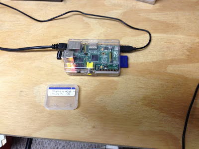
I finished up the install and was able to get the RPi to work as a wi-fi access point, with a simple firewall and nat setup and the other connection through the ethernet port.  I then started following the instructions at http://learn.adafruit.com/onion-pi to get the TOR proxy working.  The instructions do not have you rebooting the RPi at particular intervals, and that turned out to be the problem child.  As soon as I rebooted to a known state, my setup started working as advertised.  I reset my managed switch to have a port open to the outside (my psuedo-DMZ), plugged in the RPi, and restarted it.  I was able to check it out using http://www.ipchicken.com and found that my ip was coming from the output of a TOR relay.  Success ... here is a picture of the finished product for what it is worth.


Saturday, June 15, 2013

Trying to make a TOR Proxy

It looks like Adafruit came out with a tutorial on "Onion Pi". This is a TOR proxy for the Raspberry Pi. TOR is an anonymizing network. A lot of people have been showing interest in TOR since the issue with the NSA looking into people's information like email and phone calls came to light. I am just interested in the proxy because of the security aspects of it, since I am in the security game now. So later tonight I will go through the instructions.


-- LW

Monday, May 27, 2013

Music via midi?

Maybe I have added too many things that I am interested in pursuing with the RPis in my possession. However in one of the conversations with people that I work with, I now have become interested I working with the RPi in developing some midi applications, or at least using some already developed applications on the RPi.  I do posses some vintage midi gear that would come in handy here.  I have a DW8000 synthesizer, a Ground Control midi foot controller, a GMan sound module, a SQD-8 midi recorder, a TR-505 drum machine, a smaller midi controller keyboard, and a TR-1 midi thru repeater plus assorted midi cables to make it all work together.  Anyway, this shows that I have made some investment in midi gear and probably means that I should try and resurrect my keyboard abilities which if I remember correctly were sadly lacking back in the day.

I also have some midi related apps on my iPad which could be useful.  I already have a handle on the use of some Linux based midi applications including Jack and some decent sequencers.  I need to figure this one out.  Then again, maybe I should just stick to what I have been planning with the robot.

Maybe a pitch to midi converter via the RPi?  That would be an interesting use of the RPi technology.  Then you could use the RPi to interface to a guitar and play it through a midi setup or sound module. It would only take some fancy FFT processing and some comb filtering to accomplish.  Off turnings could be a problem though.

Sunday, May 26, 2013

Project #7 - Add a TOR Gateway to the Network

As part of experimentation throughout the network, I would like to add a TOR gateway on a Raspberry Pi to push information over the TOR network.

Saturday, May 25, 2013

Figured out how to make a set of tagged vlans from the Mac Mini

I was successful in determining how to set up the connection between two managed switches in my network to be a trunk with multiple tagged vlans.  I thought it might be nice to figure out how to have a trunk from my Mac Mini to one of my managed switches with the same capability.  I did determine how to add a port connection to a different vlan from the Mac via a USB to Ethernet adapter.  I decided to take the idea one step further and get a Thunderbolt to Gigabit Ethernet adapter for the purpose of getting the most speed out of the trunk line.  I plugged the adapter into Mac and fed an ethernet cable from the closest managed switch.  I then gave the adapter a fixed ip address in the home network range (same as the Mac); to have an ip address when the trunk cable is then limited to just tagged packets.  I created some VLAN Adapters on the network tool by running System Preferences -> Network, selecting the starred button on the bottom of the interface list and selecting "Manage Virtual Interfaces".  On each of these vlans I added a connection to the new adapter, selected DHCP, and set the vlan ID.  On the managed switch, at the port that my adapter was connected to, I selected the PVID line to be "VLAN only"; that makes sure that only tagged vlan packets are passed on.

In order to test this combination, I took one of the VMs that I had previously connected to the USB-Ethernet adapter and changed the bridge interface to connect to one of these new VLAN Adapters, with the same vlan ID as the USB-Ethernet adapter vlan ID.  I rebooted the VM and checked the ip that the VM had obtained.  It came back with the previous subnet that it was connected to and the same ip on that subnet (my third router remembers).  Once I was sure that the VLAN Adapter was working correctly, I moved all of the other VMs to that VLAN Adapter.  Now I have the same circuit setup as before, only this time I can reuse the trunk cable for additional tagged vlan traffic.

My next trick will be to setup a VM based router to allow traffic between vlans via the VLAN Adapters.

Tuesday, May 21, 2013

Starting to think about the IMU stick sensor

The Inertial Measurement Unit that I purchased some time ago, has a gyro, an accelerometer, a magnetometer, and a barometric pressure sensor.


I was originally thinking of using it to place onto my iRobot Create to form the basis for determining position.  Past that point, I haven't really given this that much thought.  As I am doing some research on how to use the thing, I am starting to realize that there is much that I do not know about how to use it.  There are many articles on correcting the drift errors apparent from each of these devices.  Never mind that I haven't put together an I2C interface so that I can check it out. In order to get distances from the accelerometer, you will need to do double integrations which are subject to drift in and of themselves. Some of the more interesting articles include:
It would appear from the above that I should change the way that the measurement - calculation stream is done.  I would use the Arduino to gather the info from the IMU on the I2C bus, do some preliminary calculations, and pass the information to the RPi to complete the calculations. The Raspberry Pi would have a better chance of performing the calculations.
More later.

FInally broke the code on the Vlan setup

Well, leave it to me to become confused about how to use my managed switches.  I own three Netgear GS108Ts and use them throughout my house in an effort to manage my home network.  These are a little overkill but I got them because I had this great idea about setting up multiple Vlans throughout the house and I wanted to learn a little more about configuring level 2 switches.  The problem was, up until this last weekend I really didn't have enough time to sit down and configure a "true" vlan using the boxes.  The main difficulty was figuring out how to mix untagged ports and tagged trunk lines throughout the house.  It turns out that I was reading the instructions wrong.  Yes, you heard that, I actually read instructions from time to time.

The GS108T instructions are a little vague on how to set up ports as tagged and untagged on isolated vlans.  I needed to set up ports between two managed switches with a trunk line, i.e. the packets were 802.1Q tagged, with packets going in opposite directions on the same physical ethernet line.  My problem centered around understanding what the instructions were saying, not that they are bad instructions, it's just that they left out some details or someone assumed that the user would automatically know what to do.  I am learning how to use the product correctly.  I found out that you needed to set up the ports on either side of the trunk line in the following manner:
  1. you need to set the T on each of the vlans that you want to appear as tagged on the port; the vlan numbers should be the same on either switch.
  2. on the PVID screen you need to set the acceptable frame types as "VLAN only" instead of "Admit All"; this forces the port to discard any untagged packets that appear
  3. on the PVID screen ignore the PVID field for the trunk port; this was not clear in the documentation
  4. on the PVID screen leave the ingress filtering to "Disable" as the opposite drops tagged packets that are not the id in the PVID field; since you can only have one number in the PVID field, this would not be a good choice (not clear in the documentation)
Ports that are not trunk ports, but are untagged members of the same vlan are configured as follows:
  1. you need to have a U on each of the ports represented with the vlan that you want to recieve/transmit on; note that only one vlan should be present on the untagged ports to isolate the vlan from others; this is not true of the tagged ports
  2. on the PVID screen change the PVID field to be the vlan number that you wish to have on the port
  3. on the PVID screen leave the acceptable frame types to "Admit All" for the untagged port; this will ensure that the incoming packets will be destined for the specific vlan mentioned in the PVID field
  4. on the PVID screen leave the ingress filtering to "Disable" on the untagged port; this will ensure that the rules in 802.1Q are followed for the port
Well, at least I feel better now that I can have isolated vlans running throughout the house.  If I need to move data between them, I will setup some routers to perform that function.

Added several VMs to the RPi subnet

Last night and this morning, I added a number of VMs to the Mac Mini in order to support development of the RPis and to aid in penetration testing of the subnet.  I pulled the VMs from the bitnami repository (http://www.bitnami.org) and also added some VMs that I already had working.  I am using VMWare Fusion on the Mac Mini to provide the host environment.  The VMs were:
  • RPiDev - an ubuntu VM containing bouml, cross compilers, and Arduino development packages (need to add a VNC server so that I can access the VM from one of the RPis)
  • Joomla - a CMS; here primarily for penetration testing
  • LAMP - a generic LAMP package; planning on adding ajaxplorer, a DropBox like file management system; here for file storage plus penetration testing on a generic Linux box
  • Trac - an issues tracking package
  • Subversion - a configuration management package for storage of source code
I now have the equivalent of 5 different computers running on the subnet in addition to the Raspberry Pis that I have in operation at any one moment.  In addition, I opened up a port on the outside of Router-3 so that I could connect directly to the ssh port on one of the RPis, this will aid in being able to run a VNC or ssh connection remotely.

I will probably have to change the subnet addressing.  The reason is that my home network connects to FIOS via an ActionTec router that has the same subnet addressing.  I don't want the two subnets to ever be confused with each other.

Monday, May 20, 2013

Carved out a subnet in my home network for PwnPi tests

It was raining this weekend so I decided to finish up putting together a subnet in my home network for testing the Raspberry Pi.  This will also serve as an enclave for using PwnPi to do some penetration testing.  I have decided to get back into the swing of things security wise since I am taking another certification class.  I have been wanting to learn how to do penetration testing in preparation for going after a CEH (Certified Ethical Hacker) certification.  This is outside of the ISC2 certification domain; where I already have a CISSP (Certified Information Systems Security Professional).  I have a multifold purpose for wanting to do this:
  1. I want to have a separate (logically and physically) network for penetration testing using PwnPi.
  2. Doing penetration testing will not only help me to learn but will also let me know where the weaknesses are in my network.
  3. I want to have a separate network setup to support development work on the RPi.
  4. I want to have a network setup to test out the new OpenWRT package that runs on the RPi; therefore, I need to be able to place the RPi in a router like position easily.
In my house I have three routers and three managed switches which I can use to define separate networking elements.  On one end of the house I have a Mac Mini which I use as a server for experimentation along with several other physical servers which are normally turned off until I want to do some experiments.  Why?  Because I want to learn something about networks and this way I can immerse myself in some learning topic without having to pay money for classes.  At the other end of the house is the RPi experimenters area.  I have a managed switch close to the Mac Mini and another managed switch close to the RPi experimenters area.  The three managed switches are 1GB ethernet switches, so the ethernet cable between them carries a 1GB stream.  I use this as the backbone for my home network.  I realize that it is overkill, but it allows me to do some interesting things.  For my purposes, I wanted to move one of the routers to the RPi experimenters area and set up the switches so that I could use the Mac Mini to host some virtual machines to be connected to the RPi experimenter area.  Diagrammatically it looks like this (most of the information was removed to help in the discussion):


A secondary ethernet port was added to the Mac Mini by plugging in a USB to ethernet cable.  By setting up the router between two ports on the RPi experimenter managed switch, I am able to use the router to move between two separate Vlans.  Vlans (IEEE 802.1Q) are virtual lans and can have the property that more than one vlan traffic can be moving down the same wire but yet not have packets that interfere with each other.  In my case the 1GB wire between the two managed switches have tagged vlan packets that are logically isolated from each other.  This wire carries information from the VMs running on the Mac Mini through the separate Vlan to the router (LAN side).  This in turn is mixed in with the information on the RPis.  The router provides isolation between the Vlans and in a pinch can be disconnected from the main home network; for extra security.  The RPi managed switch and router are in close proximity and I can unplug the unmanaged switch (connecting the RPis together and plug it into the managed switch on a port which is in the home network as necessary.  This is not the only separated Vlan running through my house but I need the isolation in order to continue PwnPi experiments.  Should be fun.

Tuesday, May 14, 2013

The Blackboard Design Pattern

Having gotten together a lot of the lower level patterns, I am now turning to the Blackboard design pattern itself.  I am using the POSA1 book chapter on the Blackboard design pattern.  In addition I will be using a design pattern paper entitled, "Two complementary patterns to build multi-expert systems" by Philippe Lalanda.  This allows me to think about what goes into such a design.  The Blackboard pattern layout is in the following diagram:


Notice that in this layout, the Domain knowledge sources and Control knowledge sources are separate.  The ControlPlanNet is implemented as a StateChart design pattern as is the BlackboardControl element.  The ControlPlan itself is derived from the CommandProcessor design pattern so that command are executed separate from definition and that the commands can be "named".  In addition, the ControlPlan contains a number of ControlPlanNets, allowing the Control knowledge sources to select which one is to be the current control plan.  The Top_Control_KS affords the ability to intialize both the Blackboard and the Control plan and would of course be the first knowledge source that is executed.  Again, I am trying to allow myself the luxury of defining each of these structures from xml file definitions.

Addition of StateChart to Blackboard

The StateChart pattern, from a paper by Yacoub and Ammar entitled "A Pattern Language of StateCharts," is coming along nicely.  I have the classes together and most of the code is in place, although there are some interesting issues when creating the C++ code with Bouml - not a problem with the program, just a problem with my understanding of configuring it to generate C++ the way that I want.  The class diagram is as follows:


Notice that I have incorporated the CommandProcessor as part of the actions.  The way that this works is to have the state interface control the way that the states are manipulated.  The events are enumerations (to keep it simple and to be able to cause an event to happen remotely).  The actions that are executed when a given state is entered, use the CommandProcessor to separate the commands from the overall logic of the state and at the same time provide a "named" execution.  The other nice thing about this design pattern, is the ability to create new states and actions on the fly (e.g., from the Control knowledge sources) to manipulate how the system reacts in a given instance.  Although that is a nice ability, the StateChart design pattern does allow for orthagonal state charts which are independent from each other, but can be executed in parallel.  How to eventually implement this is a TBD at this point.

Saturday, May 11, 2013

Working on the Blackboard Implementation

I have taken some time off from the electronics portion of my projects to concentrate on the software. I have been using the very affordable Bouml UML case tool (http://www.bouml.fr) to put together a design. The tool is very good at being able to generate C++ (and other languages) shells of programs. Then you take the source code generated and modify it using Qt Creator as the IDE.

I keep the design and source code on a USB stick and plug it into my Mac Mini or Work laptop, both running VMWare with Ubuntu VMs containing my code. I was able to get Bouml license keys to run a copy in both VMs, legitimate of course according to the developers license agreement. With this setup, I can work on the source code development at home, and also at the office during lunch and before work starts. Since the code is being run and tested in a Linux environment, it should transfer easily to the RPi when the time comes, via the USB stick. I will probably end up with close to a hundred classes in the design so I wanted to use some tools that made sense.

I have been working on the overall Blackboard implementation and have made several design decisions along the way.

1. I have decided to implement the Control Plan(s) as a StateChart. The advantage with this is that I can reuse the Command Processor pattern, and be able to setup portions of the plans that might be orthogonal (happening in parallel) while still being able to create the linkages via XML definitions.

2. The StateChart design pattern is developed after a paper by Yacoub and Ammar entitled "A Pattern Language of StateCharts."  I will be able to use this pattern in the Blackboard Controller implementation as well.

3. I will also be using some elements of a design pattern by Liebenau entitled "InferenceFramework: An object-oriented framework for constructing rule-based systems." He has some pretty good ideas in the paper. I hope to use his ideas in the construction of the blackboard data structure itself.

4. keeping with my original idea of building the knowledge structures and execution sequences via a definition in an XML file will go a long way in keeping my sanity as I develop test and rework the AI portion of the Robot. Besides, I like tinkering anyway.

Tuesday, April 30, 2013

Was able to get rid of the rats nest on the breadboard

I can't really say anything for my soldering skills (I wouldn't pass this for quality control), but the results look a lot better. I really like the Parallax Board of Education for prototyping.  However, having all the wires loose like this really bothers me.  I was also having problems with connectors popping loose.  Now I have a simplified place to plug in my sensors and serial connections onto the Arduino and can focus on my interface to the RPi.


Sorry for the fuzziness of the photos, it looks like the iPhone 5 didn't get them too sharp and I was using a PicFrame app to couple three photos together.  Anyway you can get a sense of what was accomplished.  I haven't done any soldering for probably 15 years, so I am a little rusty. 

After I powered up the boards (smoke test), I did manage to wipe out the IR distance sensor.  Fortunately, the IR distance sensor was not that expensive.  It appears that the IR distance sensor was drawing too much current.  I also changed back to the Pololu Mini-Maestro but I could not get it to receive commands.  It looks like I have a power issue here which needs to be resolved before I go on.  I am not sure if I need to add a 5volt regulator on the board to get power from the Vin or not.  Have to think about that one.

Wednesday, April 24, 2013

Working the Blackboard Issue

Over the last couple of days I have taken a hiatus from working on the Robot HW.  I am instead concentrating on the Blackboard implementation that I have in mind.  I have decided to wrap my design around a combination of the Blackboard, StructuredMatcher, and Command Processor design patterns.

The Command Processor design pattern, as described in POSA1 (Pattern Oriented Software Architecture, vol 1, Buschman, et al.), separates the request for a service from its execution.  The CommandProcessor component manages requests as separate objects, schedules their execution, and provides additional services.  The AbstractCommand component defines the interface of all command objects, as a minimum defining the procedure to execute a command.  In this way, individual commands can be treated as objects.  The derived command will encapsulate a function request.  In the implementation that I will be making, there are two multimaps in the CommandProcessor component.  The first one is a multimap containing a name and a pointer to an AbstractCommand.  This is the multimap illustrated on the following diagram.  The second is a multimap containing two names.  The first name is the list name and the second is the name of an abstract command contained in the first multimap.  This allows a grouping of the commands by a name.

What is missing from this design is a way to have a named list that has a prioritized listing, therefore the AbstractCommand will need to be modified to contain a priority and a strata level.  This will become more apparent as the blackboard pattern is introduced.

The Structured Matcher design pattern (from "Structured Matcher" by Eugene Wallingford, 1998) decomposes a complex decision into simpler decisions about relevant factors and then uses decisions about these factors to make the decision.  I will be using this design pattern to form the rule pattern portion of a knowledge source.  Notice that the Structured Matcher inherits from the AbstractCommand component and therefore is utilized within the Command Processor pattern.  The Structured Matcher consists of a directed, acyclic graph of simple matchers.  The Simple_Matcher component considers either the values of sub-decisions made by other simple matchers or the values of input data. A data parameter feeds into only one simple matcher.  The diagram below is a start on the design of this design pattern.  In the Structured_Matcher component there is a multimap containing a name and a pointer to a Simple_Matcher called root.  This allows the Structured_Matcher component to have a matcher list to work from.  The Simple_Matcher forms a composite design pattern with the Parameter component.  By doing this the structured matcher design pattern is composed of a list of hierarchically defined simple matchers.  One of the derived classes from the Simple_Matcher component will be a Top matcher, or top of the hierarchy. [Updated]


Finally, I will describe the Blackboard design pattern later.  I have succeeded in separating out the Domain and Control knowledge sources and I have almost completed the initial way that it will work.  However it is not complete as of this point.  I got a little bogged down in the control plan layout and how that interacts with the other design patterns.

Monday, April 22, 2013

Working on controlling the SSC32 from the Raspberry Pi

In light of the problems that I was having with reading the SSC32 pwm values from the Arduino, I thought that I might try and do the same via a serial interface to the RPi.  That is where I ran into difficulty, mostly because I was rather busy this weekend with other things.  I am trying to set up a serial terminal to communicate via a USB to RS232 interface cable to the SSC32 servo controller.  I first tried Screen but couldn't figure out how to get it to work, then I tried minicom.  I guess that I am just going to have to read up on these two programs in order to figure out the baud rate settings and commands.  I will probably try to do the same types of commands via a connection to my laptop.  But, I want to get it working on the RPi so that I can at least say it is part of the solution.  Remember, controlling the SSC32 and Mini-Maestro to move servos was not a problem, finding out the current pwm for a given servo was.

Got a new sensor in! A Sensor Stick.

I received a new sensor in the mail last week from China.  I ordered it online from Amazon at 10DOF (L3G4200D+ADXL345+HMC5883L+BMP085) Sensor Stick Breakout- for MWC/KK/ACM. As you can see from this photo, it is pretty small.  I wanted to get a gyro and accelerometer to use for an experiment that I was thinking about for the future and saw this online.


The description on the Amazon website says:

"This 10DOF sensor breakout is a very small sensor board with 10 degrees of freedom. It includes the ADXL345 accelerometer, HMC5883L magnetometer, BMP085,and the L3G4200D gyro. This break has a simple I2C interface and a mounting hole for fixing to your multi-project. just have a fund with it.
  • The ADXL345 is a small, thin, ultralow power, 3-axis accelerometer with high resolution (13-bit) measurement at up to ±16 g. Digital output data is formatted as 16 bit twos complement and is accessible through either a SPI (3- or 4-wire) or I2C digital interface. The ADXL345 is well suited for mobile device applications. It measures the static acceleration of gravity in tilt-sensing applications, as well as dynamic acceleration resulting from motion or shock.
  • The Honeywell HMC5883L is a surface-mount, multi-chip module designed for low-field magnetic sensing with a digital interface for applications such as low-cost compassing and magnetometry. The HMC5883L includes our state-of-the-art, high-resolution HMC118X series magneto-resistive sensors plus an ASIC containing amplification, automatic degaussing strap drivers, offset cancellation, and a 12-bit ADC that enables 1° to 2° compass heading accuracy.
  • The BMP085 is a high-precision, ultra-low power barometric pressure sensor for use in advanced mobile applications. It offers superior performance with an absolute accuracy of down to 0.03 hPa and using very low power consumption down to 3 µA.The BMP085 comes in an ultra-thin, robust 8-pin ceramic lead-less chip carrier (LCC) package, designed to be connected directly to a micro-controller of a mobile device via the I²C bus.
  • The L3G4200D is a 3 axis gyroscope, providing you with very high resolution (16 bit) measurements at up to 2000 degrees per second (dps). The gyroscope measures how much the device is rotating around all three axis, the range is user selectable and so can be adjusted to suit your application."
Obviously, I should be able to have fun with this.  One item that I did note was that the BMP085 is capable of outputting temperature readings along with the Barometric Pressure.  The barometric pressure readings give you a sense of altitude.  The sensor stick is apparently for use in small RC plane or helo type applications.  I plan on using most of the sensors for on the ground operation.  The sensor will give me the ability to have a sensor to work out a balance bot.  Woot!

Thursday, April 18, 2013

Turns out it might not be the Pololu Mini-Maestro after all

I did a conversion last night on the test setup.  I removed the pan/tilt servo unit and the Maestro.  In place of the Maestro, I put the Lynxmotion SSC32.  I had to make one small adjustment to the input by switching the 4 wire connection to the Maestro in favor of a 3 wire connection to the SSC32.  I then made a copy of the current sketch that I was working and started changing out the code for the Maestro.  I decided that I would use the excellent SSC32 library from Martin Peris (http://blog.martinperis.com/2011/05/libssc32-arduino-ssc32.html), well actually a modification made found at http://dl.dropbox.com/u/50461514/LibSSC32Soft.zip which uses the SoftwareSerial library.  One function that I like about the library is the ability to "gang" a number of servo instructions together so that they all execute at the same time.  The equivalent command on the Maestro is the Set Multiple Targets command, but doesn't account for a difference in speed of execution.  Same but different - don't know if I will need that in the future but I am thinking of adding a Robotic Arm which will have several servos to contend with.  In either case, I need to have more than one servo going at the same time for the sweeps.

In the process of making modifications and testing out the code, the SSC32 started exhibiting the same failure to read that the Maestro did.  I was a little puzzled until I started reading up on the NewSoftSerial documentation at arduiniana.org.  It turns out that when you have more than one software serial connection that reads, you have to let the library know to switch objects in the code.  So now I am exploring how to do precisely that.

Saturday, April 13, 2013

Command Testing for Serial Interface to Arduino

Ok, I have started implementing and testing the serial interface to the Arduino.  So far, I have coded the following sequences:

(1) 1/1/pinNumber/analogRate - to write an analog rate to a specific pin
(2) 1/2/pinNumber/digitalState - to write a digital state to a specific pin
(3) 2/1/pinNumber - to read an analog value from a specific pin (via serial)
(4) 2/2/pinNumber - to read the digital state from a specific pin (via serial)
(5) 3/1/servoPin - to read the current pose of a servo from a specific pin (not active)
(6) 3/2/servoPin/servoPose - to write a pose to a servo on a specific pin (not active)
(7) 3/3/servoPin - to detach a servo on a specific pin (not active)
(8) 3/4/servoNumber - to read the pose on a specific servo channel on the maestro
(9) 3/5/servoNumber/servoPWM - to set the pwm pose on a specific servo channel on the maestro
(10) 4/1/lowSweepIR/highSweepIR/speedSweepIR -

At first I had some problems trying to get servos to react.  I noticed that the servos were not zeroing at the beginning of the loop.  It turns out that my connection to the mini-maestro was not working.  After re-seating the connection everything started working correctly.

First test was the 3/5/servoNumber/servoPWM - worked correctly on two different servos (0 - for the Ultrasonic distance sensor, 6 - for the IR distance sensor).  I added some instrumentation via the LCD Panel and was able to see what the command was being interpreted as.  Servos moved, although there was a delay (I do have a one second feed in there).

Second test was to get the 3/4/servoNumber to work - although I could get some return values, they were not what I was expecting.  Need to do a little more homework on return values from the maestro and how I am able to read that through a serial interface.  I am getting absolutely nothing back from the Mini-Maestro.  I am even using code that I know works with the device (according to websites that have the listings).

Update: Am I up against a hardware problem?  If so, what is the least expensive way of implementing what I want.  Should I go back to the SSC-32?  The resolution in the analog domain was not that great, however, I am no longer using the Maestro to read the values from the IR or Ultrasonic distance sensors.

Tuesday, April 2, 2013

Located a library to use with HC-SR04

I was doing a search this morning and happened upon the site at http://code.google.com/p/arduino-new-ping/.  This appears to be a library with the ability to filter the HC-SR04 ultrasonic sensor.  It also appears that the author had many of the same problems that I encountered with the sensor and dealt with it with multiple pings, distance sensing, etc.  I will need some time to digest what it is capable of doing but maybe this is a better bet for a more stable read from the sensor.

Saturday, March 30, 2013

Rethinking the Blackboard Control

Well, I'm back on the Blackboard problem.  I had put together a home-brew blackboard system for another project and will be utilizing some of the patterns and development I did there.  For one thing, I was able to have the matcher portion of the system be able to be built from definitions that were contained in an xml file.  In fact, part of the process was to create new source code from xml file elements.  So I had a way of prototyping using xml, and when something became proved out I would then be able to use the same program to bootstrap new source code that could then be combined with the previous source code and compiled.  In this way, I simplified the testing that needed to be accomplished especially in the case that the problem that was being solved was not completely spelled out, i.e. the requirements were not fully thought out.

In the process of putting the home-brew blackboard together, I had not given much thought to the control issue.  The proper way of adding control to a blackboard system is to allow the control to be modified along with execution of the domain knowledge sources.  The blackboard system is then divided into two areas, one for the domain knowledge sources and one for the control plans.  The idea is to now have control knowledge sources that compete for run-time with the domain knowledge sources.  So how am I supposed to be able to get this new found control problem to work?  My thought is that I need to start with a simple control knowledge source that executes a simple control plan and places initial knowledge sources to be executed.  As the problem progresses, the elements of control and domain will play out as changes to the blackboard occur.

I am a great proponent of utilizing already proven designs, such as the concept of design patterns.  In the POSA1 book, there is a chapter on Blackboard.  I will be using this along with a design pattern paper entitled, "Two complementary patterns to build multi-expert systems" by Philippe Lalanda.  This paper was the first time that I had encountered the control and domain separation of blackboard execution.  I have later learned that BB1 was the first blackboard system to have used the idea.  I have been reading a number of papers on the subject and I am warming to the idea that this would be the way to go.  Right now my express purpose is to use this blackboard architecture to control my robot and in the process learn some things about control processing that I can reflect back into the previous project.

So if the Blackboard is utilized by the Domain knowledge sources and the Control Plan is utilized by the Control knowledge sources, how is the basic Control structure to run?  Looking at the paper I see that the Control reads both the Blackboard and Control Plan.  The knowledge sources (KS) themselves (both domain and control) will activate the Control as necessary.  The Domain knowledge sources (DKS) operate on the Blackboard and the Control knowledge sources (CKS) operate on the Control Plan.  In the original Blackboard pattern, the Control element executed a loop, determining the nextSource to execute by examination of the Blackboard and then going through the different KS which determine if they have something to offer.  Those KSs that have something to offer are placed on a list for execution and when the nextSource routine ends, the Control loop then executes each of the KS in the list.  The execution through this list, either first come first serve, or by priority, or by some other mechanism can be thought of as the control plan.

My home-brew blackboard system used a rather simplified control plan, always executing the same sequence of DSs based upon whether they had something to offer or not.  An incoming message was the trigger event that caused the whole sequence to be executed.  The incoming messages were then as a result queued for execution.  So the whole sequence, even though it was somewhat non-deterministic, ended up being an event driven case statement with matching patterns that executed as necessary.  I really did not have the concept of multiple hierarchical levels on the Blackboard such as what is in BB1.  This does not give the capability for more complex problem solving.  I need to change this capability in order to move on.

Stupid RPi Tip #4 - write it down!

If you are an experimenter like me, you try all kinds of crazy things.  More often than not, you will have more than one experiment going on at a time.  The nice thing about the Raspberry Pi is that it is so easy to change out one to do a different experiment with by simply replacing the SD Card.  This also means that sometimes you loose your place in what you were doing before and trying to remember something that you were working on two weeks ago becomes a challenge.  Answer to the dilemma, write what you do down.  I am speaking of keeping a notebook or a journal or an online notepad of some sort.  Anything that will give you the chance to regain your thoughts on where you were six months ago on a project.  Obviously this means that you need to be able to put down more than 160 characters at a time.  Think of the things you can do:

1. you can record what your ultimate goal is and what path you hope to use to accomplish that goal
2. you can record what prompted you to try this very thing
3. you can record what things you learned, and what resources you used (like SD Card numbers)
4. you can record if this particular time you were successful or not - even Thomas Edison failed over a 1000 times before he got the right combination of components to make a lightbulb, his notebooks were very handy to keep him from redoing what already didn't work
5. you can record what you hope to do in the next iteration
6. if you become famous the notes are very valuable for your memoirs and if you patent something the notes will hold up in a court of law

Robot Serial Interface Protocol

Based upon a serial interface description that I found at http://forums.trossenrobotics.com/tutorials/how-to-diy-128/complete-control-of-an-arduino-via-serial-3300/, I have decided to try doing the interface in a like manner. I could use firmata but I do not want to program the RPi in python. Here is what I have come up with so far:

Robot Interface Protocol (Serial)
1 - write
    1 - digital pin write
        "pin number"
        "1 for LOW, 2 for HIGH" --> sets pin to value, returns OK
    2 - analog pin write
        "pin number"
        "frequency (0-255)" --> sets pwm on pin to value, returns OK
    3 - LCD panel error display
        "error number"

2 - read
    1 - digital
        "pin number" --> returns digital pin value (0 or 1)
    2 - analog
        "pin number" --> returns analog pin value (0 - 1024)

3 - servo (via Maestro)
    1 - read
        "servo number" --> returns pwm value
    2 - write
        "servo number"
        "pwm value" --> sets servo to pwm value, returns OK

4 - IR distance sensor (GP2D12 and servo)
    1 - set sweep range
        "low sweep pwm value (4000 - 8000)"
        "high sweep pwm value (4000 - 8000)"
        "sweep speed (0.25 us / 10 ms)"
        "sample rate in ms" --> returns OK
    2 - set IR distance servo
        "pwm value" --> returns OK
    3 - sample IR distance sensor (raw) --> returns "IR", raw value
    4 - sample IR distance sensor (computed) --> returns "IR", computed value
    5 - start continuous sample
        -->starts sweep back and forth; returns "IR", pwm, computed,
            raw at sample rate
    6 - stop continuous sample --> returns OK
    7 - get statistics at current pwm
        "number of samples" --> returns "IR", pwm, mean, sd of computed, mean, sd of raw
    8 - display samples on LCD panel
        1 - start --> returns OK, starts showing samples on LCD panel
        2 - stop --> stops showing samples, clears LCD panel, returns OK

5 - Ultrasonic distance sensor (HC-SR04 and servo)
    1 - set sweep range
        "low sweep pwm value (4000 - 8000)"
        "high sweep pwm value (4000 - 8000)"
        "sweep speed (0.25 us / 10 ms)"
        "sample rate in ms" --> returns OK
    2 - set Ultrasonic distance servo
        "pwm value" --> returns OK
    3 - sample Ultrasonic distance sensor (raw) --> returns "UL", raw value
    4 - sample Ultrasonic distance sensor (computed) --> returns "UL",
        computed value
    5 - start continuous sample
        -->starts sweep back and forth; returns "UL", pwm, computed,
            raw at sample rate
    6 - stop continuous sample --> returns OK
    7 - get statistics at current pwm
        "number of samples" --> returns "UL", pwm, mean, sd of computed, mean, sd of raw
    8 - display samples on LCD panel
        1 - start --> returns OK, starts showing samples on LCD panel
        2 - stop --> stops showing samples, clears LCD panel, returns OK

6 - camera pan and tilt servos
    1 - set sweep range for pan
        "low sweep pwm value (4000 - 8000)"
        "high sweep pwm value (4000 - 8000)"
        "sweep speed (0.25 us / 10 ms)" --> returns OK
    2 - set sweep range for pan
        "low sweep pwm value (4000 - 8000)"
        "high sweep pwm value (4000 - 8000)"
        "sweep speed (0.25 us / 10 ms)" --> returns OK
    3 - set camera pan and tilt servos
        "pan pwm value"
        "tilt pwm value" --> returns OK
    4 - start continuous sweep
        -->starts sweep back and forth; returns OK
    5 - stop continuous sweep --> returns OK

7 - reset all to setup conditions

Friday, March 29, 2013

Distance sensor data gathering

So I was able to start gathering sensor data last night.  I wanted to start gathering information on the two distance sensors in order to be able to calibrate the system.  I have enough errors propagating around, I just wanted to understand a little more about the IR and Ultrasonic Distance Sensors themselves and how they behave and how well they measure distance.
In the picture below, you can see the IR distance sensor (GP2D12).  I was able to modify the Arduino code to give me values output on the LCD display.  My measurements were from the front of the sensor housing, that means that I will need to add the offset from the front of the sensor housing to the center of the servo rotation point to get an accurate reading on the measurements.


For the ultrasonic distance sensor (HC-SR04) the measurements will be the same.  I will measure from the front of the sensor housing to the target and will add the distance from the front of the sensor housing to the center of the servo rotation point.


Wires: now that I have everything hooked up on the Lexan plate, the wire jumble on the top of the Arduino breadboard is pretty much a mess.  I am thinking of getting a proto board and putting headers on it in order to not have the jumble on top.  You can see what I mean by the picture below.


When I took the values from the IR distance sensor, I was surprised to notice how much the value changed with each sample.  The measurements are as follows:

Distance Measure1 Measure2 Measure3
2 7.24 7.22 7.26
2.25 6.76 6.72 6.72
2.5 6.84 6.91 6.82
2.75 7.54 7.64 7.68
3 8.23 8.66 8.57
3.25 9.23 9.18 9.15
3.5 9.97 9.97 9.36
3.75 10.95 10.92 10.85
4 11.39 11.32 11.46
4.25 12.28 12.24 12.24
4.5 12.84 13.05 12.84
4.75 13.72 13.72 13.72
5 14.39 14.29 14.24
5.5 15.67 15.73 15.67
5.75 16.63 16.26 16.5
6 17.08 17.14 17.08
6.25 17.96 17.89 17.89
6.5 18.47 18.4 18.18
6.75 19.01 18.7 19.01
7 19.9 20.15 19.98
7.25 20.33 20.24 20.33
7.5 21.52 21.42 21.42
7.75 21.81 21.71 21.9
8 23.26 23.04 23.04
9 25.9 25.51 26.03
10 28.63 28.79 29.11
11 32.89 32.29 33.5
12 36.64 36.4 35.92
13 35.92 31.92 36.4
14 40.65 40.65 40.65


Even though I took three measurements at each distance, the values pretty much vary pretty wildly.  A simplified graph of these measurements are as follows:

Actually, I should probably try and swap the x and y axis.  The x axis is the distance and the y axis is the measured values.  True to the data sheet, values that approach around 2 inches from the front of the sensor will change up and values over about 12 inches seem to start varying wildly.  In between, from 2 to 12 inches, the values seem to be steady and are almost linear given the formula in the sampling routine.  The values that return from the Ultrasonic sensor seem to vary even more crazily (see video below).

What I am learning from this is that I might have to rethink how the robot will follow the wall with the sensor data that I am seeing.