- WiFi Bridge - this will be needed to connect the non-WiFi equipment, like the Edgerouter-12, to the WiFi network
- MQTT Server - this would provide an MQTT instance at the WiFi level on the ER12 router for some automation things
- Home Assistant Server - this would provide an HA instance through the ER12 router
- L2TP IPSec Endpoint - this would provide a connection for my laptops from anywhere in the community through the ER12 router
- Raspberry Pi WiFi Endpoint - L2TP IPSec GRE based endpoint that isolates the Ethernet connection of the RPi from the WiFi portion which runs over the campus WiFi network; it also allows a point to point connection between RPi endpoints with multiple networking protocols running over it on whatever vlans I desire; this might possibly be implemented by an RPi Zero W/USB plug
- Plex Server - this would provide Plex capability through the ER12 router
- NextCloud Server - this would provide file and project services through the ER12 router

This is a blog mostly about techie things, what I am doing to my apartment network on the cheap, IOT, 3D Printing, Raspberry Pis, Arduinos, ESP32, ESP8266, Home Automation, Personal Weather Stations, Things That Go Bump in the Night, and some side issues that need discussing. Remember, sometimes the journey to an end is as much fun as the goal achieved!
Showing posts with label Router. Show all posts
Showing posts with label Router. Show all posts
Friday, December 24, 2021
Possible Networking Changes in an All WiFi Environment
Since the retirement village will have only WiFi connection, there will be some things that I will need to add to make the setup easier for the future. It seems that I will be able to talk between devices over the WiFi network, including all over the campus. I am counting on this to be able to do some interesting network things. So there would need to be some of the following developed:

Sunday, February 14, 2021
Project #23 - What Makes Sense to ChangeUp in the Network?
What makes sense in the changeup of my network?
I do have a problem in the way that things are partitioned:
1. vlans are just that, they are setup to not have connection to each other. This is by design, and I went out of my way when I setup my Edgerouter-12 to force vlan isolation even though by default vlans can talk to each other.
2. I actually setup some vlans so that the elements in those vlans would only be able to talk outside the router to the internet and not to each other. This was a security design.
3. I made sure that vlans that were isolated to other vlans were not able to modify any of the settings on my Edgerouter-12 except for the admin vlan. This was a security design.
4. I have a couple of specific computers that are allowed to contact other vlans. This was by design and allows me to monitor equipment as necessary without having to give all my equipment the same level of access. This was a security design.
5. The above way of partitioning has resulted in some problems with being able to get to certain servers. I actually need the following:
- I need to be able to get to port 8123 of my HA-IOT server, on the IOT vlan, from the LAN3 vlan which contains my iPhones, iPads, and laptops.
- My HA-IOT server needs to get to the data servers in the Server vlan
- My Plex server resides in the Server vlan and both the Media and the LAN3 vlan need to get to it
- My Media equipment needs to get to the data servers in the Server vlan
- For testing purposes I need to have some Docker containers in the Development vlan be able to get to the MQTT server on the HA-IOT server in the LAN3 vlan
- My iPhones, iPads, and laptops on the LAN3 vlan need to be able to get to Media equipment on the Media vlan
- Some of these alternate connections are going to require the device to be on the same subnet
So, this means that there needs to be overlap between the different vlans, but at the same time it needs to be controlled. I do have an additional Edgerouter-X which I can use for that purpose. This will be an exploration of what I can accomplish. This Edgerouter-X will not be used as a normal router, but will in fact be the way that I can provide a controlled interface between vlans. If the router is removed, then everything will go back to the way it was before. This will also give me a chance to try out zone based routing on the Edgerouter-X.
Thursday, June 20, 2019
Network General - added an EdgeRouter X as an OpenVPN server
I had attempted to use one of the GL-iNet routers (AR800M) to act as an OpenVPN server on my network. I setup one of the vlans from the Main Router and had a whole lot of problems with the setup. I discovered that the EdgeRouter-X (ER-X) was only $65 from MicroCenter and a lot of people indicated that is was an easy setup for OpenVPN. I decided that what I would do was setup a vlan from the Cisco router with one of my unused vlans that flows throughout the network. So I designated one of my many vlans to be an “OpenVPN passthrough”. This will be similar in concept to the No-Mans Land vlan that I have been using for some time. The “OpenVPN passthrough” vlan will be setup so that you cannot change the Cisco router and you cannot access any other vlan. I will also punch some ports through the Cisco router to the Wan port of the ER-X. The OpenVPN setup is shown at https://help.ui.com/hc/en-us/articles/115015971688-EdgeRouter-OpenVPN-Server. I have found this to be a very easy setup. I also generated some additional OpenVPN client cents to use with my cell phones, iPads, and laptops.
Wednesday, April 18, 2018
Added some patch panels to the network over the weekend
Well, I broke down and finally added a couple of patch panels (PP) to the homelab over the weekend. I was getting tired of having to reconstruct connections whenever I wanted to move equipment from one room to the next. My homelab is distributed across the house and I like to think that I can move and update things at will. The problem was that I could not conveniently switch things around because of having to move existing Ethernet cables from one location to the next. What I needed was a set of Ethernet cables that didn't move but still allowed me to connect at will, hence the use of patch panels.
Right now I am concentrating on getting the minimal number of patch panels up along with keeping equipment and connections the same. This is little more than routing an Ethernet cable to a patch panel and then using a patch cable to go from the PP to the device. In the throes of putting the initial two PP together, I made the mistake of routing a piece of equipment to the patch panel as though it were part of the infrastructure. I now know to keep lines primarily from PP to PP within the network.
I started out with a 16 port and one 24 port PP that I placed in two locations. The first location was in the tool room where my main switch is located, that got a 16 port PP. The main switch is like the hub for most of the other managed switches. The second location was part of the computer room shelf where I am not concentrating most of my efforts. I originally drew up a diagram of what I wanted to do first followed by a diagram of where I wanted to go. I followed the first diagram pretty closely but ended up with a lot of differences due to the position of the ports and other equipment that was around it.
Right now I am concentrating on getting the minimal number of patch panels up along with keeping equipment and connections the same. This is little more than routing an Ethernet cable to a patch panel and then using a patch cable to go from the PP to the device. In the throes of putting the initial two PP together, I made the mistake of routing a piece of equipment to the patch panel as though it were part of the infrastructure. I now know to keep lines primarily from PP to PP within the network.
I started out with a 16 port and one 24 port PP that I placed in two locations. The first location was in the tool room where my main switch is located, that got a 16 port PP. The main switch is like the hub for most of the other managed switches. The second location was part of the computer room shelf where I am not concentrating most of my efforts. I originally drew up a diagram of what I wanted to do first followed by a diagram of where I wanted to go. I followed the first diagram pretty closely but ended up with a lot of differences due to the position of the ports and other equipment that was around it.
Sunday, September 17, 2017
Checking Power for the Computer Room
So today I am checking the power coming to my new computer room. I have cleared out most of the things that were in the room, enough to be able to get around and move my equipment into the room. There were two lines that I uncovered coming from the main panel that went into the tool room. One went to two outlets through a breakout box: power for the main managed switch and a 4 socket setup on the workbench. Since I will not be using the workbench much after I move the 3D printer into the computer room, I should be okay with the power draw. The line is on a 20 amp circuit and the switch does not draw that much. Having the 3D printer in the computer room allows me to setup an exhaust outlet for when I start doing stinky plastics like ABS, nylon, and PETG. The other line coming from the main panel goes to a breakout box that is tied to power going into the computer room. I need to trace down the wires to make sure that I understand where they are going to. I am hoping that there is not a lot of activity on this power line.
I have been looking for a power meter that I can use to determine what the current draw is on each of these lines so that I can make sure not to exceed 80%. That should keep the lines cool enough for continuous usage. I went to Loews last night and got some 12 gauge power wire to hook the first line I mentioned to some of the other outlets in the room. I need to determine what the power requirements are for the following groupings of equipment:
1. Computer Rack
- 1500 watt APC
- Server One - generic PC with 7 Ethernet ports
- Server Two (future buy) - probably a NUC device
- Raspberry Pi Cluster: 4 RPis, plus 6 usb connector power supply
- 16 port 1GB managed switch
- 8 port 1GB managed switch
- 8 port 1GB switch
- Two WD myCloud devices (4TB and 3TB) plus One backup usb drive (4TB)
2. Hutch
- Smaller APC unit
- Mac Mini
- Two monitors: one with dual HDMI inputs
- powered speakers
- PC laptop docking station
- external 4TB drive
- external DVD burner
- old 3in1 printer for scanning
- Apple TV 3/Roku
- 8 port 1GB managed switch
3. DIY Electronics Table
- Smaller APC unit
- 8 port POE switch
- 8 port 1GB managed switch
- 4-unit HDMI switch
- PC power supply for bench
- One monitor w/attached RPi
- 6 usb connector power supply for RPis/Arduinos
- RPi with 7" LCD screen for monitoring
4. 3D Printer (in Lack table enclosure)
- 3D printer
- OctoPi setup with camera
- power supply for OctoPi
- Ethernet connection from OctoPi to the Hutch managed switch
Friday, March 25, 2016
Adding A New Printer and an Updated Cisco Router
In the last couple of days I have ordered a new printer and a new router.
My trusty HP 8500g printer decided on its own to stop printing in a draft mode. It can still print somewhat readable from the front panel (e.g., the network report) but from a remote connection it doesn't come up correctly. This was driving me to drink while I was trying to get some resume's printed. I finally gave up in disgust and ordered a HP OfficeJet Pro 8620 All-in-One Color Photo Printer with Wireless. Like my HP 8500g, it has Ethernet connectivity and wireless connection (I usually don't use the wireless). But there are some new bells and whistles like the AirPrint capability built in (working with my Apple products) and the legal size scan bed. I also noticed that there are some newer software drivers and the printing is much faster. The scanning seems to be more reliable. It had a 4.3 out of 5 rating for 1102 respondents, which is very high.
The new router is an Cisco RV325. The RV220W that I have has reached the end of life and will only be supported with patches until 2020. I got the RV325 because it has a fall-over mode to 3G/4G enabled cell usb adapter. In addition, it has 14 usable ports which may be setup to use VLANs. The additional 2 ports are used for dual WAN connections (one being a fall-over). Looking at the throughput it was around 800Mbps with about 50 Mbps for IPSec connections. Since I am planning on setting up an IPSec VPN to the house, this seemed like a good purchase. It has a 3.8 out of 5 rating for 50 respondents. Update: response time is very quick on this router, much faster than my RV220W. I will probably push the RV220W into service as a WAP only box.
My trusty HP 8500g printer decided on its own to stop printing in a draft mode. It can still print somewhat readable from the front panel (e.g., the network report) but from a remote connection it doesn't come up correctly. This was driving me to drink while I was trying to get some resume's printed. I finally gave up in disgust and ordered a HP OfficeJet Pro 8620 All-in-One Color Photo Printer with Wireless. Like my HP 8500g, it has Ethernet connectivity and wireless connection (I usually don't use the wireless). But there are some new bells and whistles like the AirPrint capability built in (working with my Apple products) and the legal size scan bed. I also noticed that there are some newer software drivers and the printing is much faster. The scanning seems to be more reliable. It had a 4.3 out of 5 rating for 1102 respondents, which is very high.
The new router is an Cisco RV325. The RV220W that I have has reached the end of life and will only be supported with patches until 2020. I got the RV325 because it has a fall-over mode to 3G/4G enabled cell usb adapter. In addition, it has 14 usable ports which may be setup to use VLANs. The additional 2 ports are used for dual WAN connections (one being a fall-over). Looking at the throughput it was around 800Mbps with about 50 Mbps for IPSec connections. Since I am planning on setting up an IPSec VPN to the house, this seemed like a good purchase. It has a 3.8 out of 5 rating for 50 respondents. Update: response time is very quick on this router, much faster than my RV220W. I will probably push the RV220W into service as a WAP only box.
Monday, February 8, 2016
Added Raspberry Pi Cluster for Experimenting
I just added a Raspberry Pi Cluster (4 RPis) to experiment with BGP and IPSec VPNs. My thought was to have a No-Mans Land VLAN running through the house in which I could tap into with the cluster. Since the NML vlan traffic wouldn't touch any of the other vlans it would make it easy to try out different types of routing protocols. I could also use one of the RPis to act as an IPSec VPN server to connect from the outside to the NML vlan. I could set it up so that it might be on a DMZ or other path. I am therefore not constrained even though I have double routers in my network. The cluster can be seen in this picture taken this morning:

When I was putting this together I was running some tests on a bench with the following layout:

I moved the cluster and router (acting as an 8 port managed switch) to an area where I have a UPS so that the power would be filtered. The first item on the list is to get a reasonable IPSec VPN running, hopefully using StrongSwan with some decent encryption, say AES256. Since the router has a WAN port, I can use that any time that I need to update the RPis in the cluster - just add a wire and then take it away. I did discover one issue though, I am going to have to remove the Mac Mini from the NML vlan because I noticed that all of the ports that were open on my personal vlan were open on the NML vlan. I don't know how to correct that so for now, after I get the IPSec VPN setup, I will remove the Mac Mini so I can reduce the probability that someone will hack into my network.

When I was putting this together I was running some tests on a bench with the following layout:
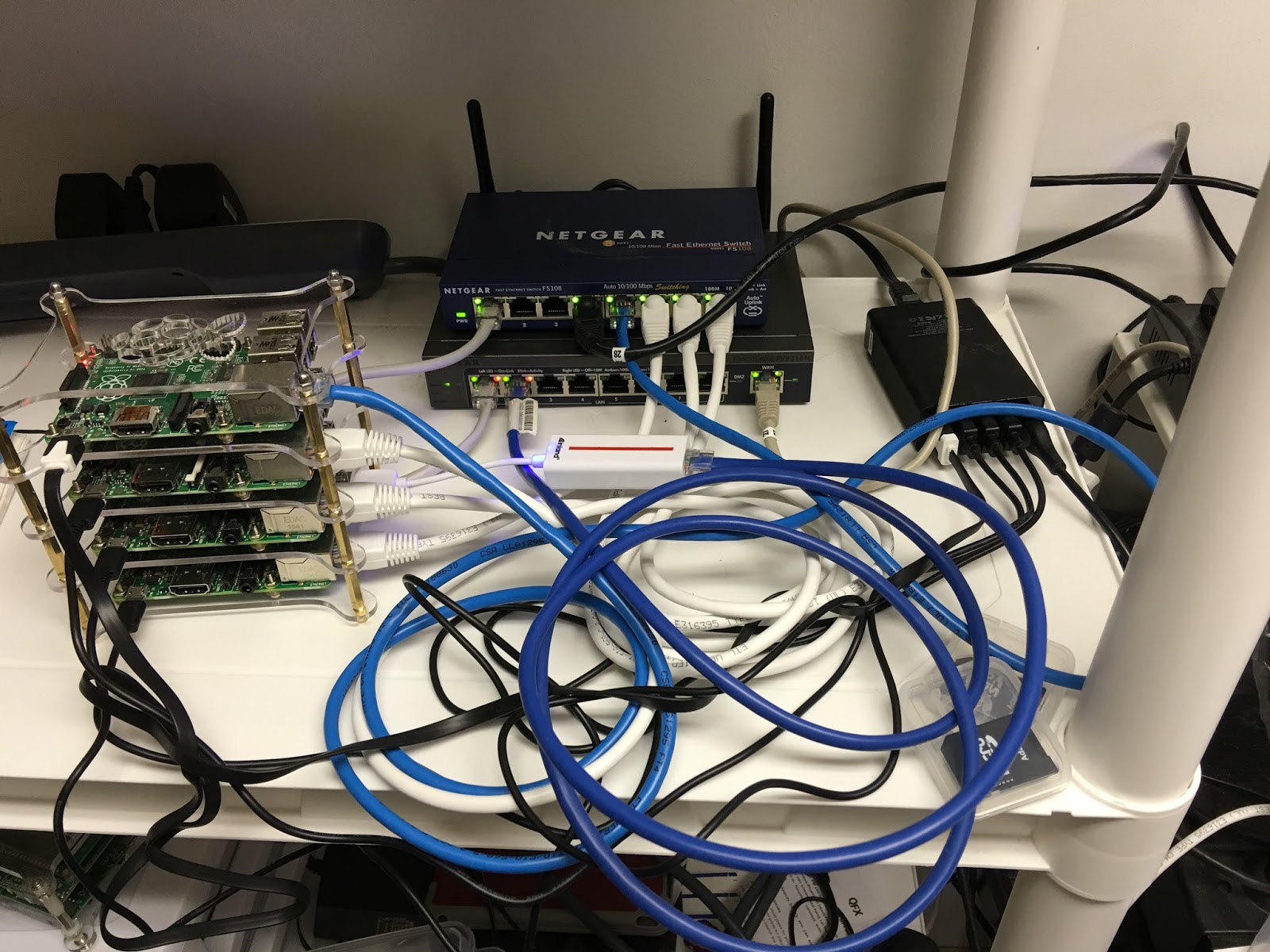
I moved the cluster and router (acting as an 8 port managed switch) to an area where I have a UPS so that the power would be filtered. The first item on the list is to get a reasonable IPSec VPN running, hopefully using StrongSwan with some decent encryption, say AES256. Since the router has a WAN port, I can use that any time that I need to update the RPis in the cluster - just add a wire and then take it away. I did discover one issue though, I am going to have to remove the Mac Mini from the NML vlan because I noticed that all of the ports that were open on my personal vlan were open on the NML vlan. I don't know how to correct that so for now, after I get the IPSec VPN setup, I will remove the Mac Mini so I can reduce the probability that someone will hack into my network.
Saturday, January 23, 2016
TravelRouter#2 - Updated to Routed Client Mode using LuCI
I was pretty pleased with how easy it was to put the GL.iNet 6416a into a Routed Client Mode using LuCI (generic instructions are here). The basic connection was through an Ethernet cable from my laptop to the router plugged into the LAN port. The full-up connection is shown in the image:

In the expedience of time I will explain the process in the following paragraphs.
(1) connect the router via an Ethernet plugged into the LAN port and the other end placed into a USB to Ethernet adapter on the laptop.
(2) disconnect the laptop from all Ethernet connections except for the router connection.
(3) log into the router with credentials using your browser; select Network -> WiFi.
(4) click on the Scan button next to the "Generic MAC80211 802.11bgn (radio0)" line. Select the WiFi network that you wish to join by clicking on the "Join Network" button.
(5) leave "Replace Wireless Configuration" checked, this will ensure that everything is replaced. Enter the wpa2 passphrase. Make sure that WAN is selected; this will ensure that the wireless setup is associated with the WAN connection on the router. Select save.
(6) When the next screen comes up, make sure that WAN is selected. Click on Save and Apply.
(7) At the next screen you should see the selected WiFi under the "Generic..." line. Next, click on the Add button next to the "Generic..." line. Select LAN to associate with this new WiFi SSID. Change the name from"OpenWRT" if you desire a different SSID for your LAN network connection.
(8) select Wireless Security tab to setup the WPA2 data. Select WPA2-PSK for encryption and "Force TKIP and CCMP (AES)" from the dropdown next to Cipher. Add the passphrase as necessary. Click on Save and Apply. This will bring you back to the screen with the "Generic..." line. You should see both the SSID of the WiFi you are connected to on the WAN side, and the SSID for the LAN side. At this point you are set up.
That is pretty easy setup for OpenWRT. Next, I got to figure out a couple of different setups including one with OpenVPN back to my house.

In the expedience of time I will explain the process in the following paragraphs.
(1) connect the router via an Ethernet plugged into the LAN port and the other end placed into a USB to Ethernet adapter on the laptop.
(2) disconnect the laptop from all Ethernet connections except for the router connection.
(3) log into the router with credentials using your browser; select Network -> WiFi.
(4) click on the Scan button next to the "Generic MAC80211 802.11bgn (radio0)" line. Select the WiFi network that you wish to join by clicking on the "Join Network" button.
(5) leave "Replace Wireless Configuration" checked, this will ensure that everything is replaced. Enter the wpa2 passphrase. Make sure that WAN is selected; this will ensure that the wireless setup is associated with the WAN connection on the router. Select save.
(6) When the next screen comes up, make sure that WAN is selected. Click on Save and Apply.
(7) At the next screen you should see the selected WiFi under the "Generic..." line. Next, click on the Add button next to the "Generic..." line. Select LAN to associate with this new WiFi SSID. Change the name from"OpenWRT" if you desire a different SSID for your LAN network connection.
(8) select Wireless Security tab to setup the WPA2 data. Select WPA2-PSK for encryption and "Force TKIP and CCMP (AES)" from the dropdown next to Cipher. Add the passphrase as necessary. Click on Save and Apply. This will bring you back to the screen with the "Generic..." line. You should see both the SSID of the WiFi you are connected to on the WAN side, and the SSID for the LAN side. At this point you are set up.
That is pretty easy setup for OpenWRT. Next, I got to figure out a couple of different setups including one with OpenVPN back to my house.
Friday, January 15, 2016
TravelRouter #1 - I Bought a GL-iNet 6426A Travel Router
After some looking around, I ended up buying a GL-iNet 6416A Travel Router from Amazon for $24. What intrigued me about this router was the (1) OpenWRT based system and (2) the ability to reflash it with a new version of OpenWRT if I wanted. So the first thing that I did after getting the router was to reflash it (instructions here) with the latest Chaos Calmer version. This eliminated the tweeks that the company had placed on the router, but I wanted to customize my own. BTW, the company provided a very nice suite of abilities for the novice. This router was also the basis for the nefarious TOR routers that showed up on kickstarter a couple of years ago. Those routers were tossed because they claimed original prototypes and manufacturing when in fact they were just repackaging the GL-iNet 6416A. The following is an image of the router from rednerd.com (his site has a very good description of how to add TOR to this router).

I also immediately set the system to allow ssh connections on the LAN side. The next tweek was to update the software listings and setup LuCI for web interface. I did that through ssh (instructions here). I next setup the router with my own SSID and WPA2 password (without enabling the wireless). The interface allowed me to choose between putting the wireless on the LAN or the WAN side of things, I chose LAN. After all that, it would appear that I have about 11.95 MB more space for software. That means that I can do a lot with it.
My main thought is to setup some standard configurations with some kind of selection through the web interface to easily set the router to what I want. That may take some doing. More Later.
I also immediately set the system to allow ssh connections on the LAN side. The next tweek was to update the software listings and setup LuCI for web interface. I did that through ssh (instructions here). I next setup the router with my own SSID and WPA2 password (without enabling the wireless). The interface allowed me to choose between putting the wireless on the LAN or the WAN side of things, I chose LAN. After all that, it would appear that I have about 11.95 MB more space for software. That means that I can do a lot with it.
My main thought is to setup some standard configurations with some kind of selection through the web interface to easily set the router to what I want. That may take some doing. More Later.
Monday, December 21, 2015
Learning BGP - Thinking of adding a number of RPi BGP routers to the network
I have been toying with a way of cross-pollinating the packets on my home network. Right now I am at a quandary on how to allow computers on my Media VLAN to talk to the printer on the Pers VLAN. It is an interesting problem and one that strangely enough has something to do with two projects that I am working on at work. I want to explore how to route information from one network to another given that the subnet on each end of the gateway have the same ip addresses, but yet must remain different. I think the key to this something approaching the BGP protocol perhaps with some gateway translation in the middle. More later.
Monday, February 10, 2014
Manuevered Some connections around to make way for a special VLAN
Over the weekend I made some changes to my network in preparation for venturing out as an Anonymous user. My real reason for doing this is to see if I can somehow escape Google's tracking. This is an interesting twist since I am using Blogger to blog on and that in turn is owned by Google.
I have been reading up on the DarkNet and what that really means. Since I am getting more involved with security I thought it might be a good thing to explore various anonymization networks, e.g. TOR, to see how they function and what to expect when I am out there. This obviously involves assuming a pseudo id to mask who I really am - new territory, haven't ventured there before.
I was able to set up a VLAN on the ActionTec router from http://support.actiontec.com/doc_files/Creating_an_Ethernet_VLAN.pdf on the ActionTec site. The instructions are a little old but after a bit of trying out different things, I was able to have a VLAN (tagged) on a specific port with a DHCP server and a localized subnet. I then proceeded to change the wiring around a little, moving my MacMini ethernet connections from the tail-end switch to the one just before it. I set up the first switch to have a tagged input port then connected an Ethernet cable from the ActionTec to it. Next I set up the switch to send the new VLAN down a trunk line to the second switch and from there to the third and last switch. In the process of doing this I consolidated a number of Ethernet connections to one switch which actually speeded up my access to the outside. I was also able to reduce the usage of the last switch in the stream to make it more experimenter like, including adding the new VLAN.
I now have a line from the ActionTec router that has only one port (I will be putting a laptop on this port) isolated from my network that I will be able to use for Anonymity.
I have been reading up on the DarkNet and what that really means. Since I am getting more involved with security I thought it might be a good thing to explore various anonymization networks, e.g. TOR, to see how they function and what to expect when I am out there. This obviously involves assuming a pseudo id to mask who I really am - new territory, haven't ventured there before.
I was able to set up a VLAN on the ActionTec router from http://support.actiontec.com/doc_files/Creating_an_Ethernet_VLAN.pdf on the ActionTec site. The instructions are a little old but after a bit of trying out different things, I was able to have a VLAN (tagged) on a specific port with a DHCP server and a localized subnet. I then proceeded to change the wiring around a little, moving my MacMini ethernet connections from the tail-end switch to the one just before it. I set up the first switch to have a tagged input port then connected an Ethernet cable from the ActionTec to it. Next I set up the switch to send the new VLAN down a trunk line to the second switch and from there to the third and last switch. In the process of doing this I consolidated a number of Ethernet connections to one switch which actually speeded up my access to the outside. I was also able to reduce the usage of the last switch in the stream to make it more experimenter like, including adding the new VLAN.
I now have a line from the ActionTec router that has only one port (I will be putting a laptop on this port) isolated from my network that I will be able to use for Anonymity.
Thursday, November 7, 2013
Issue with the FVS318N Router
I am slowly learning how to incorporate the FVS318N. However, now I discover that there is apparently no way to setup VLAN to VLAN rules. The router gives you the ability to make some rules for LAN to WAN, LAN to DMZ, and DMZ to WAN, but no LAN to LAN (or in my case VLAN to VLAN). I did discover that there is a CLI (command line interface document that details some newer aspects of the router, but a cursory look into the command set did not give me the impression that there was a way to setup LAN to LAN rules.
My main motivation in setting up the LAN to LAN rules is to allow the Media VLAN to be able to access the Plex server running on my Mac Mini which is on a completely separate VLAN. In addition to that, I use the Mac Mini as the main workstation for modifying the routers and switches in my home network. Yea, I know, way too much - but I enjoy doing what I do. I was thinking that I might try my hand at setting up either a Raspberry Pi router or setup a VM on the Mac Mini to do the routing. What would be perfect is if I could do it on the new FVS318N. This router will be able to replace about 3 devices if I succeed.
Update: I figured out that if I use a "1 to 1 NAT" from a router, I can have an IP show up in one VLAN from a device resident in another VLAN with a different IP. I am currently working the issue using a VM on the Mac Mini to do the routing with Shorewall. Once I get that up and running, I will transfer it to a Raspberry Pi router which will be on all the time.
My main motivation in setting up the LAN to LAN rules is to allow the Media VLAN to be able to access the Plex server running on my Mac Mini which is on a completely separate VLAN. In addition to that, I use the Mac Mini as the main workstation for modifying the routers and switches in my home network. Yea, I know, way too much - but I enjoy doing what I do. I was thinking that I might try my hand at setting up either a Raspberry Pi router or setup a VM on the Mac Mini to do the routing. What would be perfect is if I could do it on the new FVS318N. This router will be able to replace about 3 devices if I succeed.
Update: I figured out that if I use a "1 to 1 NAT" from a router, I can have an IP show up in one VLAN from a device resident in another VLAN with a different IP. I am currently working the issue using a VM on the Mac Mini to do the routing with Shorewall. Once I get that up and running, I will transfer it to a Raspberry Pi router which will be on all the time.
Monday, November 4, 2013
Found an interesting thing while using one of my routers
This weekend while fooling around with one of my routers, I chanced to put the WAN input of the main router onto my DMZ vlan. I was able to have a full connection to the outside after I got rid of the first ethernet cable that I was using (it did not register as being connected). When I connected the main router to my DMZ vlan, I noticed that I had a GHz connection (thanks to the GBit switch that I was using) and I was able to connect to the outside with no apparent slowdown of the speed.
I still have an issue though, because I set up the ActionTec router to route specific ports to my main router. However, with this new connection, I have a means of controlling pretty much everything in the house. I was wondering how I might fit my new FVS318N router into the mix. Originally, I was going to put it upstairs and replace 3 devices (my main router, the upstairs switch and the router I use with the media vlan downstairs). The media vlan router is connected into the DMZ vlan in the downstairs bedroom. I was going to use the FVS318N to replace it as I could set up multiple dhcp servers, each tuned to a separate vlan. This has been the issue throughout my house as I expand the capabilities of my setup.
Sounds like I need to explore a little more of what vlans can do for me.
I still have an issue though, because I set up the ActionTec router to route specific ports to my main router. However, with this new connection, I have a means of controlling pretty much everything in the house. I was wondering how I might fit my new FVS318N router into the mix. Originally, I was going to put it upstairs and replace 3 devices (my main router, the upstairs switch and the router I use with the media vlan downstairs). The media vlan router is connected into the DMZ vlan in the downstairs bedroom. I was going to use the FVS318N to replace it as I could set up multiple dhcp servers, each tuned to a separate vlan. This has been the issue throughout my house as I expand the capabilities of my setup.
Sounds like I need to explore a little more of what vlans can do for me.
Tuesday, May 21, 2013
FInally broke the code on the Vlan setup
Well, leave it to me to become confused about how to use my managed switches. I own three Netgear GS108Ts and use them throughout my house in an effort to manage my home network. These are a little overkill but I got them because I had this great idea about setting up multiple Vlans throughout the house and I wanted to learn a little more about configuring level 2 switches. The problem was, up until this last weekend I really didn't have enough time to sit down and configure a "true" vlan using the boxes. The main difficulty was figuring out how to mix untagged ports and tagged trunk lines throughout the house. It turns out that I was reading the instructions wrong. Yes, you heard that, I actually read instructions from time to time.
The GS108T instructions are a little vague on how to set up ports as tagged and untagged on isolated vlans. I needed to set up ports between two managed switches with a trunk line, i.e. the packets were 802.1Q tagged, with packets going in opposite directions on the same physical ethernet line. My problem centered around understanding what the instructions were saying, not that they are bad instructions, it's just that they left out some details or someone assumed that the user would automatically know what to do. I am learning how to use the product correctly. I found out that you needed to set up the ports on either side of the trunk line in the following manner:
The GS108T instructions are a little vague on how to set up ports as tagged and untagged on isolated vlans. I needed to set up ports between two managed switches with a trunk line, i.e. the packets were 802.1Q tagged, with packets going in opposite directions on the same physical ethernet line. My problem centered around understanding what the instructions were saying, not that they are bad instructions, it's just that they left out some details or someone assumed that the user would automatically know what to do. I am learning how to use the product correctly. I found out that you needed to set up the ports on either side of the trunk line in the following manner:
- you need to set the T on each of the vlans that you want to appear as tagged on the port; the vlan numbers should be the same on either switch.
- on the PVID screen you need to set the acceptable frame types as "VLAN only" instead of "Admit All"; this forces the port to discard any untagged packets that appear
- on the PVID screen ignore the PVID field for the trunk port; this was not clear in the documentation
- on the PVID screen leave the ingress filtering to "Disable" as the opposite drops tagged packets that are not the id in the PVID field; since you can only have one number in the PVID field, this would not be a good choice (not clear in the documentation)
- you need to have a U on each of the ports represented with the vlan that you want to recieve/transmit on; note that only one vlan should be present on the untagged ports to isolate the vlan from others; this is not true of the tagged ports
- on the PVID screen change the PVID field to be the vlan number that you wish to have on the port
- on the PVID screen leave the acceptable frame types to "Admit All" for the untagged port; this will ensure that the incoming packets will be destined for the specific vlan mentioned in the PVID field
- on the PVID screen leave the ingress filtering to "Disable" on the untagged port; this will ensure that the rules in 802.1Q are followed for the port
Thursday, December 6, 2012
Strange Port Openings Appeared
While I was going through the motions of trying to get the Ceton echo (CE) to authenticate against my WMC pc, I encountered so many problems that I started turning off all my controls. In particular, I turned on uPnP on my router and took down my Windows firewall on the WMC pc. After I that I was successful in getting the CE to authenticate.
This morning I was fiddling with the router and I remembered that I still had uPnP running. When I went to turn it off, I noticed that the Teredo tunneling protocol had been activated from both the WMC pc and the CE ip addresses. (I looked it up) The Teredo tunneling protocol is a way of tunneling through a router that has IPv6 turned off, which is the case on my router. I turned off IPv6 because of all the things that I had read concerning bypassing routers. Symantec has a nice writeup on how this protocol can be used by botnets, viruses, etc. to wreak havoc on a network. Needless to say, I eliminated the Teredo ports and turned off uPnP altogether.
I am assuming that the CE will still work with the WMC PC because Microsoft should have already given out certs for the connection. There should no longer be a need to pass back any information. I will test it out tonight but the theory is that this setup should work without having uPnP or those ports available. Otherwise, I am really concerned that I have an opening to the outside that I did not authorize.
BTW, what are people who aren't tech knowledgeable supposed to do?
-- LW
This morning I was fiddling with the router and I remembered that I still had uPnP running. When I went to turn it off, I noticed that the Teredo tunneling protocol had been activated from both the WMC pc and the CE ip addresses. (I looked it up) The Teredo tunneling protocol is a way of tunneling through a router that has IPv6 turned off, which is the case on my router. I turned off IPv6 because of all the things that I had read concerning bypassing routers. Symantec has a nice writeup on how this protocol can be used by botnets, viruses, etc. to wreak havoc on a network. Needless to say, I eliminated the Teredo ports and turned off uPnP altogether.
I am assuming that the CE will still work with the WMC PC because Microsoft should have already given out certs for the connection. There should no longer be a need to pass back any information. I will test it out tonight but the theory is that this setup should work without having uPnP or those ports available. Otherwise, I am really concerned that I have an opening to the outside that I did not authorize.
BTW, what are people who aren't tech knowledgeable supposed to do?
-- LW
Sunday, December 2, 2012
First Vlan Tryout Setup
After having borked the router last time when I was trying to set up a vlan, I am now going to be a little more cautious. To that end, I am going to list out all of the steps and the proper sequence so that I don't get into trouble. My first tryout is to set up a vlan from a VMware Stack through two managed switches, and then to the final router. The following steps will be necessary:
1. Setup the Stack to connect through vlan8.
2. Setup the Mac Mini to put vlan8 out as a tagged stream.
3. Setup the Mac Mini to be able to get to any system in vlan8, but not the other way around (iptables equiv.).
4. Setup the first switch to accept vlan8 packets on the same port as the Mac Mini.
5. Setup the first switch to pass the tagged vlan8 to the second switch on a trunk.
6. Setup the second switch to receive the tagged vlan8 packet on the trunk and pass it as a tagged packet to the port on which the router resides.
7. Setup the router to receive the tagged vlan8 packet on the trunk line and pass it on through the NAT firewall to the outside.
8. The router should be set up so that it does not allow cross communication between vlan8 and any other vlan on the router.
9. Setup the router with a port forward to the VMware stack.
That is basically what I need to accomplish, now on to figuring out the particulars of each.
Update: 12/3/2012 - I have performed steps 4, 5, and 6 with the two switches. That was the easy part of this sequence. I have decided to make the subnets reflective of the vlan number by using the vlan number as one of the 4 octets. Not sure whether to use C, B, or A addressing scheme. I have also performed step 2 to have the vlan8 output as a tagged stream. When I went to perform step 1 I set the Stack to the vlan that I had created in step 2, I encountered no problems. When I changed the DHCP address to the new vlan8 subnet that is when the problems began. More later.
- LW
1. Setup the Stack to connect through vlan8.
2. Setup the Mac Mini to put vlan8 out as a tagged stream.
3. Setup the Mac Mini to be able to get to any system in vlan8, but not the other way around (iptables equiv.).
4. Setup the first switch to accept vlan8 packets on the same port as the Mac Mini.
5. Setup the first switch to pass the tagged vlan8 to the second switch on a trunk.
6. Setup the second switch to receive the tagged vlan8 packet on the trunk and pass it as a tagged packet to the port on which the router resides.
7. Setup the router to receive the tagged vlan8 packet on the trunk line and pass it on through the NAT firewall to the outside.
8. The router should be set up so that it does not allow cross communication between vlan8 and any other vlan on the router.
9. Setup the router with a port forward to the VMware stack.
That is basically what I need to accomplish, now on to figuring out the particulars of each.
Update: 12/3/2012 - I have performed steps 4, 5, and 6 with the two switches. That was the easy part of this sequence. I have decided to make the subnets reflective of the vlan number by using the vlan number as one of the 4 octets. Not sure whether to use C, B, or A addressing scheme. I have also performed step 2 to have the vlan8 output as a tagged stream. When I went to perform step 1 I set the Stack to the vlan that I had created in step 2, I encountered no problems. When I changed the DHCP address to the new vlan8 subnet that is when the problems began. More later.
- LW
Friday, November 16, 2012
Less Than Happy with the New Router
I have installed the new router in my home network. The ActionTec router from Verizon is somewhat of a disappointment, first of all it only has 100MHz Ethernet even though the user manual says it gets 1GHz. Second, it has a port open to the world which from my readings is not there because "Verizon's servers will poll the address and update the software in the router"; it seems to be there because Verizon has a direct connection to a facility down south which is an internal intelligence gathering organization. Not only that but it apparently a web based server, undocumented in the router user manual, which is only protected by username and password. I consider that a security breach into my home network.
I will be attempting to close this port down in the near future. If I am not able to do that, I will be putting all of my network behind my other router and DMZing the connection to it from the ActionTec. If the organization down south needs to see what I have in my network they can contact me directly. Conspiracy theories aside, I just don't trust something that I know nothing about and is well known across the internet. The port is also the same port that is used by at least two botnets for their control. Also the username and password combo is subject to attack. That is why I don't allow management of any router I have directly from an Internet connection. Hopefully Verizon will understand.
Update: [12/2/2012] it would appear that I may be completely wrong here. The ActionTec router has a TR-069 capability which allows it to be controlled as part of a larger scale system for remote management of end-user devices. (see http://en.wikipedia.org/wiki/TR-069)
- LW
I will be attempting to close this port down in the near future. If I am not able to do that, I will be putting all of my network behind my other router and DMZing the connection to it from the ActionTec. If the organization down south needs to see what I have in my network they can contact me directly. Conspiracy theories aside, I just don't trust something that I know nothing about and is well known across the internet. The port is also the same port that is used by at least two botnets for their control. Also the username and password combo is subject to attack. That is why I don't allow management of any router I have directly from an Internet connection. Hopefully Verizon will understand.
Update: [12/2/2012] it would appear that I may be completely wrong here. The ActionTec router has a TR-069 capability which allows it to be controlled as part of a larger scale system for remote management of end-user devices. (see http://en.wikipedia.org/wiki/TR-069)
- LW
Saturday, October 20, 2012
A Little Router Conversion
After diagramming what I wanted to do in the network, I decided to change out the second and third routers (both Linksys WRT54GLs) from OpenWRT to DD-WRT. I did this in order to remain compatible across all routers that I had in the house. Also I wanted to learn something about setting up a router for vlans and multiple wireless SSIDs. The conversion from OpenWRT to DD-WRT is simple, you download the appropriate dd-wrt binary and update the flash rom from the OpenWRT menu, reboot, press the reset switch for about 15 seconds and let the router boot up. When the router comes up it will be a http://192.168.1.1 with a default password; then you log in and reset the parameters to your liking.
My requirements for the first of these routers are simple but will require a number of changes to the normal setup; most of the instructions for these can be found in the tutorials at http://www.dd-wrt.com/wiki/index.php/Tutorials:
(1) I need port 1 to be a fall back in case I do something stupid, so no vlan
(2) I want port 2 to be the trunk port with vlans 5, 6, 8, and 9 tagged (802.1Q)
(3) I want port 3 to be vlan 6 with no tags [connect this to port 2]
(4) I want port 4 to be vlan 8 with no tags [connect this to port 2]
(5) I want vlan 5, 6, 8, and 9 to be separate from each other
(6) I want the wireless to come in on vlan 5 with no tags [connect this to port 2]
(7) Later on I want to have a separate wireless SSID on vlan 9 with no tags [connect to port 2]
(8) I will be using the router as a WAP, therefore the WAN port should be deactivated
First I activated the SSH server on the router and logged in as user. I started off with setting up four new vlans numbered 5, 6, 8, and 9. To do this you activate a hardware name:
root@DD-WRT:~# nvram show | grep vlan.*hwname
vlan1hwname=et0
size: 22970 bytes (9798 left)
vlan0hwname=et0
root@DD-WRT:~# nvram set vlan5hwname=et0
root@DD-WRT:~# nvram set vlan6hwname=et0
root@DD-WRT:~# nvram set vlan8hwname=et0
root@DD-WRT:~# nvram set vlan9hwname=et0
root@DD-WRT:~# nvram show | grep vlan.*hwname
vlan6hwname=et0
vlan9hwname=et0
vlan5hwname=et0
vlan1hwname=et0
vlan8hwname=et0
size: 23034 bytes (9734 left)
vlan0hwname=et0
Next, I change the port settings around so that ports are connected in a different arrangement. The WRT54GL router has the ports numbered backwards according to the instructions on the DD-WRT site. To start with, we associate ports with vlans:
root@DD-WRT:~# nvram show | grep vlan.*ports
vlan0ports=3 2 1 0 5*
vlan1ports=4 5
size: 23034 bytes (9734 left)
root@DD-WRT:~# nvram set vlan6ports="2t 1 5*"
root@DD-WRT:~# nvram set vlan8ports="2t 0 5*"
root@DD-WRT:~# nvram set vlan0ports="3 5*"
root@DD-WRT:~# nvram show | grep vlan.*ports
vlan6ports=2t 1 5*
vlan0ports=3 5*
vlan1ports=4 5
size: 23066 bytes (9702 left)
vlan8ports=2t 0 5*
Now we associate in the opposite direction to complete the setup:
root@DD-WRT:~# nvram show | grep port.*vlans
port5vlans=0 1 16
port3vlans=0 18 19
port1vlans=0 18 19
port4vlans=0 18 19
port2vlans=0 18 19
size: 23066 bytes (9702 left)
port0vlans=1 18 19
root@DD-WRT2:~# nvram set port5vlans="0 1 6 8 16"
root@DD-WRT2:~# nvram set port2vlans="6 8 16 18 19"
root@DD-WRT2:~# nvram set port3vlans="6 18 19"
root@DD-WRT2:~# nvram set port4vlans="8 18 19"
root@DD-WRT2:~# nvram show | grep port.*vlans
port5vlans=0 1 6 8 16
port3vlans=6 18 19
port1vlans=0 18 19
port4vlans=8 18 19
size: 23298 bytes (9470 left)
port2vlans=6 8 16 18 19
port0vlans=1 18 19
Lastly we do a commit and reboot the router.
root@DD-WRT:~# nvram commit
nvram_commit(): end
root@DD-WRT:~# reboot
At this point, we have the vlans on the correct ports but the connections are not correct to the trunk line. A little more work is involved.
--LW
Thursday, October 18, 2012
Well Fudge - My Router Doesnt Do Port VLANs
Ok, just went through some sites looking for solutions on how I can do a port - trunk metaphor with my Buffalo WZR-HP-G300NH router. It turns out that because it uses an Atheros chipset, it doesn't have the ability to separate out the ports from one another. So if I set up a tagged (802.1Q) vlan on one port, all of the ports will have the same tagging applied to them. I wish I had known this when I first bought the router.
Now I have re-arranged my network setup to only have one port into the Buffalo router which will be trunk fed, i.e. all the packets will have tags. I will also be able to have separate DHCP servers for each tagged vlan to put the addresses into separate subnets. The other two routers I have are Linksys WRT54GLs which have Broadcom chipsets and will support the port - trunk metaphor. They are 100MHz ethernet but that is less important in the lower portions of my network. So with a little re-arrangement I have resolved the main issue. Now I can use the Netgear managed switch to force my little vlans to appear.
-- LW
Now I have re-arranged my network setup to only have one port into the Buffalo router which will be trunk fed, i.e. all the packets will have tags. I will also be able to have separate DHCP servers for each tagged vlan to put the addresses into separate subnets. The other two routers I have are Linksys WRT54GLs which have Broadcom chipsets and will support the port - trunk metaphor. They are 100MHz ethernet but that is less important in the lower portions of my network. So with a little re-arrangement I have resolved the main issue. Now I can use the Netgear managed switch to force my little vlans to appear.
-- LW
Tuesday, October 16, 2012
Oops - Operator Error - Did Not Look at Examples
Over the weekend, I changed out the software on the router coming into my house. I was able to get Internet access working for all of the units in my house but was not able to get my VPN working correctly. I tried all kinds of things including restarting the router, restarting the VPN server, checking wires, etc. It wasn't until this morning that I figured it out.
In the setup for Port Forwarding, there was a entry in each port field asking for the source network. I just assumed that it meant WAN if I wanted the Internet. The field was there to limit the IP addresses to a certain range of values, not the overall VLAN name. It sometimes pays to look at the help files. In this case, nowhere in the documentation does it tell you that is what the field is for; glad I now know.
I updated the software to set up some VLANs running through the house and keep certain flows like TV STB flows from interacting with Wireless traffic and personal computer traffic.
Now I am onto getting the VLANs working
- LW
In the setup for Port Forwarding, there was a entry in each port field asking for the source network. I just assumed that it meant WAN if I wanted the Internet. The field was there to limit the IP addresses to a certain range of values, not the overall VLAN name. It sometimes pays to look at the help files. In this case, nowhere in the documentation does it tell you that is what the field is for; glad I now know.
I updated the software to set up some VLANs running through the house and keep certain flows like TV STB flows from interacting with Wireless traffic and personal computer traffic.
Now I am onto getting the VLANs working
- LW
Subscribe to:
Posts (Atom)