

This is a blog mostly about techie things, what I am doing to my apartment network on the cheap, IOT, 3D Printing, Raspberry Pis, Arduinos, ESP32, ESP8266, Home Automation, Personal Weather Stations, Things That Go Bump in the Night, and some side issues that need discussing. Remember, sometimes the journey to an end is as much fun as the goal achieved!
Showing posts with label HomeLink HA Interface. Show all posts
Showing posts with label HomeLink HA Interface. Show all posts
Saturday, May 30, 2020
HomeLink HA Interface #8 - Now have Working Interface
From the point of getting NodeRed to run, I ran several tests to figure out how to publish mqtt messages that could be sent to my home-assistant server. Since there are three buttons on the clicker for testing, here are the flows that I used:


Friday, May 15, 2020
HomeLink HA Interface #7 - altered way to put NodeRed and setup interface
I was having difficulties with getting the docker version of node-red to do what I wanted to do with the Raspberry Pi. It seems like I wasn't able to update Node.js and the docker repository wasn't helping. So I decided to abandon the docker version of node-red, but keep docker, run node-red natively, and set it up to command the interface to send MQTT topics to my Home-Assistant server.
-- remove the docker-compose elements
sudo docker-compose down -rmi all
The preceding command not only stops all containers setup using docker-compose, but it removes the images after stopping the process.
Now that I have accomplished this, I move to install NodeRed on the Raspberry Pi natively.
-- install nodered, node.js
sudo apt update
sudo apt install build-essential git
bash <(curl -sL https://raw.githubusercontent.com/node-red/linux-installers/master/deb/update-nodejs-and-nodered)
This did manage to take a long time due to this being an RPi Zero.
-- remove the docker-compose elements
sudo docker-compose down -rmi all
The preceding command not only stops all containers setup using docker-compose, but it removes the images after stopping the process.
Now that I have accomplished this, I move to install NodeRed on the Raspberry Pi natively.
-- install nodered, node.js
sudo apt update
sudo apt install build-essential git
bash <(curl -sL https://raw.githubusercontent.com/node-red/linux-installers/master/deb/update-nodejs-and-nodered)
This did manage to take a long time due to this being an RPi Zero.
Thursday, September 5, 2019
HomeLink HA Interface #6 - finishing off the Interface including coding
So this project has been on the back burner for some time. I never got the hardware over to something besides a breadboard, and I did not have the software running in the RPi0W. I have a three day weekend coming up and I thought I might revive it and get it working with the Home-Assistant setup in my house. I am trying to at least get the interface to my car working with the lights on the porch using this setup. At this point I am thinking my best bet will be to load docker into the raspberry pi zero w and spin up a container of nodered to interface with the RPi0W and to send out packets to my MQTT server when buttons are pressed on my Subaru rear view mirror. I decided to use an 8GB micro SD for this project since not much will change.
1. First things first - install Buster using the Win32DiskImager (see Stupid RPi Tip #5)
2. Next update the OS (Buster went from test to stable, so have to use apt instead of apt-get first)
sudo apt update
sudo apt-get upgrade
3. Next install docker
curl -sSL https://get.docker.com | sh
4. now that we have docker installed, need to get a working version of nodered in a docker container; also, it might be nice to have Portainer running to check status; we will use docker-compose for this (I usually set everything up in a directory in /srv/docker/); docker-compose.yml file is as follows:
version: '3'
services:
portainer:
container_name: portainer
image: portainer/portainer
volumes:
- /srv/docker/portainer:/data
- /var/run/docker.sock:/var/run/docker.sock
ports:
- "9000:9000"
nodered1:
container_name: node-red-1
restart: unless-stopped
image: nodered/node-red-docker
user: root
volumes:
- /srv/docker/node-red-1/user:/data
- /etc/localtime:/etc/localtime:ro
ports:
- "1880:1880"
Prior to launching DockerCompose we need to have a directory /srv/docker/node-red-1/ and /srv/docker/portainer/ ready to go.
mkdir /srv/docker/portainer
mkdir /srv/docker/node-red-1
Now put the docker-compose.yml file into /srv/docker/ directory. Next launch DockerCompose
DockerCompose up
This should get us started with node-red running in the container
To Be Continued ...
1. First things first - install Buster using the Win32DiskImager (see Stupid RPi Tip #5)
2. Next update the OS (Buster went from test to stable, so have to use apt instead of apt-get first)
sudo apt update
sudo apt-get upgrade
3. Next install docker
curl -sSL https://get.docker.com | sh
4. now that we have docker installed, need to get a working version of nodered in a docker container; also, it might be nice to have Portainer running to check status; we will use docker-compose for this (I usually set everything up in a directory in /srv/docker/); docker-compose.yml file is as follows:
version: '3'
services:
portainer:
container_name: portainer
image: portainer/portainer
volumes:
- /srv/docker/portainer:/data
- /var/run/docker.sock:/var/run/docker.sock
ports:
- "9000:9000"
nodered1:
container_name: node-red-1
restart: unless-stopped
image: nodered/node-red-docker
user: root
volumes:
- /srv/docker/node-red-1/user:/data
- /etc/localtime:/etc/localtime:ro
ports:
- "1880:1880"
Prior to launching DockerCompose we need to have a directory /srv/docker/node-red-1/ and /srv/docker/portainer/ ready to go.
mkdir /srv/docker/portainer
mkdir /srv/docker/node-red-1
Now put the docker-compose.yml file into /srv/docker/ directory. Next launch DockerCompose
DockerCompose up
This should get us started with node-red running in the container
To Be Continued ...
HomeLink HA Interface #5 - Ooops!
I decided to get back into putting the interface together and finishing out the prototype. I also decided to pull it apart from the breadboard and put the hardware onto an Adafruit perma-proto board that would interface directly to the RPi0W. Little did I know that I would make a strategic mistake.
First of all, I pulled up Fritzing and put the wiring up on the board (visually) as shown:

As shown, I added three red LEDs to be able to pulse as a visual reference when the HomeLink channel is selected. I also place a 7805 power tab in the lower right hand corner of the board. If the board looks weird it's because it is the size normally used for a regular sized RPi. And yes, it does overhang. The 5 lines are actually a cable that goes from the breadboard to the LiftMaster. These can be seen in the following images:
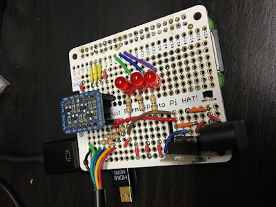
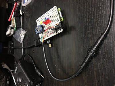
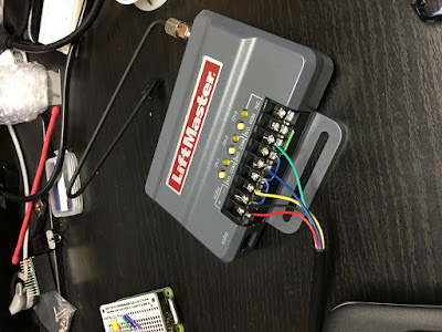
The Ooops in the title stems from the fact that when I applied power (9v to the breadboard connector) I encountered the following:
What I have since surmised is that the peripherals that I had plugged into the RPi0W were drawing way more than the 1 amp max the 7805 could handle. So what I plan on doing is removing the 7805 and replacing it with a 5v 2.5a supply that plugs into the RPi0W connected with a step up converter to push 9v to the LiftMaster which only draws 40ma.
First of all, I pulled up Fritzing and put the wiring up on the board (visually) as shown:

As shown, I added three red LEDs to be able to pulse as a visual reference when the HomeLink channel is selected. I also place a 7805 power tab in the lower right hand corner of the board. If the board looks weird it's because it is the size normally used for a regular sized RPi. And yes, it does overhang. The 5 lines are actually a cable that goes from the breadboard to the LiftMaster. These can be seen in the following images:


The Ooops in the title stems from the fact that when I applied power (9v to the breadboard connector) I encountered the following:
- while the RPi0W was booting, I tried out the clicker with the LiftMaster and it was working fine
- the bootup of the RPi0W seemed to be going fine, then it rebooted, and then rebooted, etc.
- I reached over to turn off the monitor I was using and burned my finger on the 7805 poking up from the breakboard
- I went and got my temperature laser reader and when I rebooted the RPi0W I was reading in short order about 150 degrees Fahrenheit. Way too much current was being drawn.
What I have since surmised is that the peripherals that I had plugged into the RPi0W were drawing way more than the 1 amp max the 7805 could handle. So what I plan on doing is removing the 7805 and replacing it with a 5v 2.5a supply that plugs into the RPi0W connected with a step up converter to push 9v to the LiftMaster which only draws 40ma.
Monday, August 20, 2018
HomeLink HA Interface #4 - Slowdown to use a breadboard
So life happened again. I wish I could just get down with development and not have to stop for something, but that is never the case in my life. Maybe when I am retired it will get better; hopefully more time available for my hobbies. Right now I am in the middle of a kitchen update and work activities that are ramping up again.
I decided to go ahead and get a couple of Raspberry Pi Zero breadboards to see if I can solder the required resistors and the level shifter, along with a couple of breadboard electrical connectors. I have it in mind to run power to the RPi breadboard and then connect the 850LM to the breadboard as well. That way, the power goes to one location and is distributed from there. It would be nice if I could find a simple board that provides 5v power without being huge.
That being said, I fritzed a layout using the Adafruit quarter proto-board. I used pretty much the same connections, except that I purposefully put most of the power traffic cop on the proto-board. So there are now five entities that will need to go into a 3D print, counting the LiftMaster 850LM. The fritzing layout (not showing the 850LM) follows:

This was pretty much as simple as I could get it. I am using a slightly different Buck-Converter than the Adafruit one shown in the Fritzing diagram, but the principle is the same (9v -> 5v power for the RPi Zero W). I am assuming at this point that when the relay switches and drops the voltage to zero that the 9v power will not drop below the point where the RPi will "brown out." The resistors are 220 ohm which will give a draw of 40 ma from the 9v power supply during the relay switch. Note that the 850LM channel 1 is tied to GPIO4, channel 2 is tied to GPIO5, and channel 3 is tied to GPIO6 on the RPi Zero W. The fritzing RPi is a Zero but that is okay for illustration purposes since the GPIO pinouts are the same. The use of a RPiZW is for wifi access in my IOT vlan.

This was pretty much as simple as I could get it. I am using a slightly different Buck-Converter than the Adafruit one shown in the Fritzing diagram, but the principle is the same (9v -> 5v power for the RPi Zero W). I am assuming at this point that when the relay switches and drops the voltage to zero that the 9v power will not drop below the point where the RPi will "brown out." The resistors are 220 ohm which will give a draw of 40 ma from the 9v power supply during the relay switch. Note that the 850LM channel 1 is tied to GPIO4, channel 2 is tied to GPIO5, and channel 3 is tied to GPIO6 on the RPi Zero W. The fritzing RPi is a Zero but that is okay for illustration purposes since the GPIO pinouts are the same. The use of a RPiZW is for wifi access in my IOT vlan.
Wednesday, August 15, 2018
HomeLink HA Interface #3 - Started the breadboarding process using an RPiZW, Buck converter, and 850LM
So I was able to start breadboarding the whole HomeLink HA Interface last night with mixed success. I first of all did the tests in HA #2, followed by connecting everything up to my breadboard test setup. The overall setup that I am going for looks like this:

The converter board will actually be a breadboard connected to the RPiZW gpio pins. I am planning to initially mount the Down Converter (Buck) to the same breadboard. However, I need to get everything set up first before moving the parts to the RPiZW breadboard. So, the initial physical setup looks like this:

The RPiZW is rather small compared to the LiftMaster 850LM, so piggy backing everything on one breadboard for the prototype is probably ok. I also need to figure out a model to print from my 3D printer to contain everything.
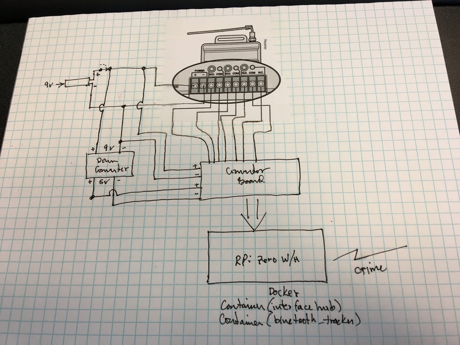
The converter board will actually be a breadboard connected to the RPiZW gpio pins. I am planning to initially mount the Down Converter (Buck) to the same breadboard. However, I need to get everything set up first before moving the parts to the RPiZW breadboard. So, the initial physical setup looks like this:

The RPiZW is rather small compared to the LiftMaster 850LM, so piggy backing everything on one breadboard for the prototype is probably ok. I also need to figure out a model to print from my 3D printer to contain everything.
Tuesday, August 14, 2018
HomeLink HA Interface #2 - Experiments with the LiftMaster 850LM
So I decided to go ahead and test out the LiftMaster 850LM to see what I was up against. This device will become central to how I am going to interface my home automation system to my car. I have always been a little upset that there were no interface devices to link my car to other than a simple switch or a garage door. That is shallow thinking on the part of the automotive industry and the people who make garage door devices. Anyway I digress.
The 850LM is going to be used to detect button clicks from my car and convert those clicks to MQTT messages that will be sent to my home-assistant controller via an MQTT broker. I expect to interface this on a Raspberry Pi Zero W (RPi0W) using its gpio pins. However, there are a couple of issues that need to be resolved. The gpio pins on the RPi take 3.3v and the lowest voltage DC that the 850LM can handle is 9v. Fortunately, I noticed previously that the Adafruit bi-directional level shifter can take a high side voltage up to 10vDC. That means that I can use the level shifter between the 850LM and the RPi0W. The main reason that I want to use the RPi0W for this interface is that I can run the software under a Docker container, and allow for another container to House a Bluetooth proximity sensor / MQTT setup. Note that the RPi0W needs a 5v DC power source, but generates its own 3.3v power for the gpio.
The 850LM has a power port as well as a screw connection marked plus and minus. It has a total of three relay connections; the first two having NO / GND screw terminals and the third having NO / GND / NC screw terminals. So my first question was how do the power port and power screw terminals relate. The second question was when the relays switch is it momentary (governed by how long you press the button on the car), is it momentary (fixed close then open time), or is it more of an on / off switch (changes as you click the car button). Fortunately, I should be able to use a remote control to do the testing.
Test 1: I powered up the 850LM using a 5v to 9v usb cable that I had lying around by plugging it into the power port. I had to use an adapter because the center pin on the power port was thick (white size). Once powered up, I had no problem setting up the remote control by following the 850LM instructions (click yellow button on 850LM, led next to button flashes, click button on remote, led goes out). Once I did this, a click on the remote caused the relay to close and then open on its own. So I answered the second question. It makes sense because most garage door controllers have wall switches that momentarily close a connection which starts the garage door motor running.
Test 2: I then checked the power terminal pins and discovered that there was on voltage in the millivolt range. This means that I cannot power the 850LM and draw power from these terminals when the 9v supply is plugged into the power connection.
Test 3: while clicking on the remote, I checked the voltage levels appearing between the NO / GND terminals. This did not measure any change from zero volts. This means that I will need to use a pull-up resistor for transitioning on the level shifter. It also means that I will need to deal with negative logic; high showing up on the gpio means False / 0 / not clicked, and low means True / 1 / clicked. I might end up using interrupts instead of running everything through a loop in order to not interfere with other container programs.
Test 4: I connected my 9v power source to the power screw terminals. I checked the on / off with my remote and everything worked out just fine. So I will be connecting the 9v source (via a barrel to screw terminal adapter) to these terminals, along with the input side of a Buck converter (to give 5v from the 9v source) and some connection wires to power up the high side of the level shifter. What I may do instead is put everything on a breadboard connected to the RPi0W gpio and minimize the connections needed (use the breadboard as the connection points for all of it).
I wonder if I can mount the Buck converter on the breadboard as well, that would save some space for me. I am also concerned that the Buck converter might interfere with the functioning of the RPi, but I will have to test that out as everything is built.
I wonder if I can mount the Buck converter on the breadboard as well, that would save some space for me. I am also concerned that the Buck converter might interfere with the functioning of the RPi, but I will have to test that out as everything is built.
Thursday, July 12, 2018
HomeLink HA Interface #1 - Development of a RPi Based Integration with a Liftmaster 850LM and Home Assistant
Not long ago I became interested in Home Automation. This occurred as a result of making plans to add some more living space to my house. I figured if I was going to spend some money on my house I should add some new capabilities as well. I found out about Home-Assistant and was intrigued by the idea of being able to integrate disparate manufacturer's devices into the same mix along with being able to control them from the same source. The problem with going to any one vendor is that they want you in their ecosystem; hence when you have many devices you end up with say many apps on your phone. I wanted to do everything with one, or do it by voice, but be able to pick and choose what device I want where. The war between Insteon and Z-Wave be damned.
So here is the brain-fart. I have a Subaru Forester that has a set of HomeLink buttons on the auto-dimming rear-view mirror. I don't have a garage, but I do have a porch with lights. So, my first interaction was to add a Chamberlain light switch to the porch lights which I can command to go on and off from one of the HomeLink buttons. Now I can turn on the porch lights when I get home late, and turn them off when I get in the house. That was very little effort and I did that before I decided to go into Home Automation. I removed a dimmer switch to put in the Chamberlain light switch. I miss the ability to dim the lights on the front porch. Why can't I have both a dimming capability and a HomeLink turn on and off ability. In fact, why can't I use the HomeLink buttons to key off a "scene" like turn on the porch lights (if it's dark outside), turn off the living room lights, lock the door, set the alarm, wait for x minutes so you can get out of the driveway before turning off the porch lights? Then, when I come home I just use a different HomeLink button to do the reverse? Hence my desire to integrate something into the Home Automation sequence using HomeLink.
I was able to locate / buy a Liftmaster 850LM switch which has the ability to integrate with the HomeLink switches and garage door opener remote controls. Normally it is used to control a garage door, but interestingly enough, I can sense the latches with an ESP8266 / Arduino / Raspberry Pi (take your pick) and push out the state of those latches using MQTT to the Home Assistant automation platform. If I want, I discovered that the 850LM can run on as little as 9 volt DC input. The Adafruit 757 bi-directional logic level converter has a max input on the high side of 10 volts which means that I could go through the 757 from the 850LM to whatever device I want to sense the state change. I can then use the chosen device to use MQTT to send state information changes to the Home-Assistant center. If I am real smart I can use a length of time timer that a HomeLink button is held down to increase the number of different states that I can report and if I use an RPi with Docker I can do other things at the same time. Oh, and two clicks within 1 second would give me a third level, but let’s not get ahead of ourselves. Anyway, it's worth investigating.
So now to get from Brain-Fart to working system.
So here is the brain-fart. I have a Subaru Forester that has a set of HomeLink buttons on the auto-dimming rear-view mirror. I don't have a garage, but I do have a porch with lights. So, my first interaction was to add a Chamberlain light switch to the porch lights which I can command to go on and off from one of the HomeLink buttons. Now I can turn on the porch lights when I get home late, and turn them off when I get in the house. That was very little effort and I did that before I decided to go into Home Automation. I removed a dimmer switch to put in the Chamberlain light switch. I miss the ability to dim the lights on the front porch. Why can't I have both a dimming capability and a HomeLink turn on and off ability. In fact, why can't I use the HomeLink buttons to key off a "scene" like turn on the porch lights (if it's dark outside), turn off the living room lights, lock the door, set the alarm, wait for x minutes so you can get out of the driveway before turning off the porch lights? Then, when I come home I just use a different HomeLink button to do the reverse? Hence my desire to integrate something into the Home Automation sequence using HomeLink.
I was able to locate / buy a Liftmaster 850LM switch which has the ability to integrate with the HomeLink switches and garage door opener remote controls. Normally it is used to control a garage door, but interestingly enough, I can sense the latches with an ESP8266 / Arduino / Raspberry Pi (take your pick) and push out the state of those latches using MQTT to the Home Assistant automation platform. If I want, I discovered that the 850LM can run on as little as 9 volt DC input. The Adafruit 757 bi-directional logic level converter has a max input on the high side of 10 volts which means that I could go through the 757 from the 850LM to whatever device I want to sense the state change. I can then use the chosen device to use MQTT to send state information changes to the Home-Assistant center. If I am real smart I can use a length of time timer that a HomeLink button is held down to increase the number of different states that I can report and if I use an RPi with Docker I can do other things at the same time. Oh, and two clicks within 1 second would give me a third level, but let’s not get ahead of ourselves. Anyway, it's worth investigating.
So now to get from Brain-Fart to working system.
Subscribe to:
Posts (Atom)